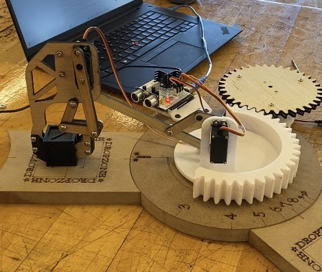
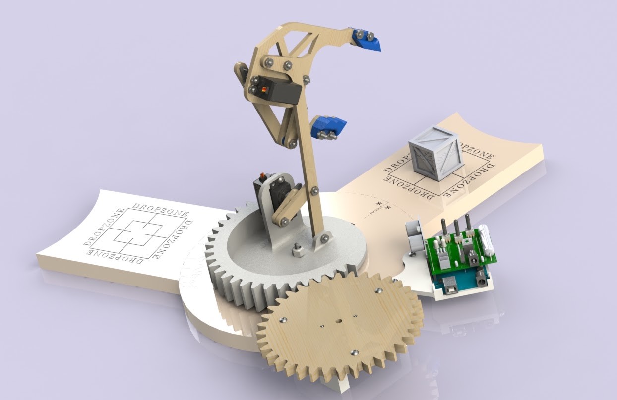
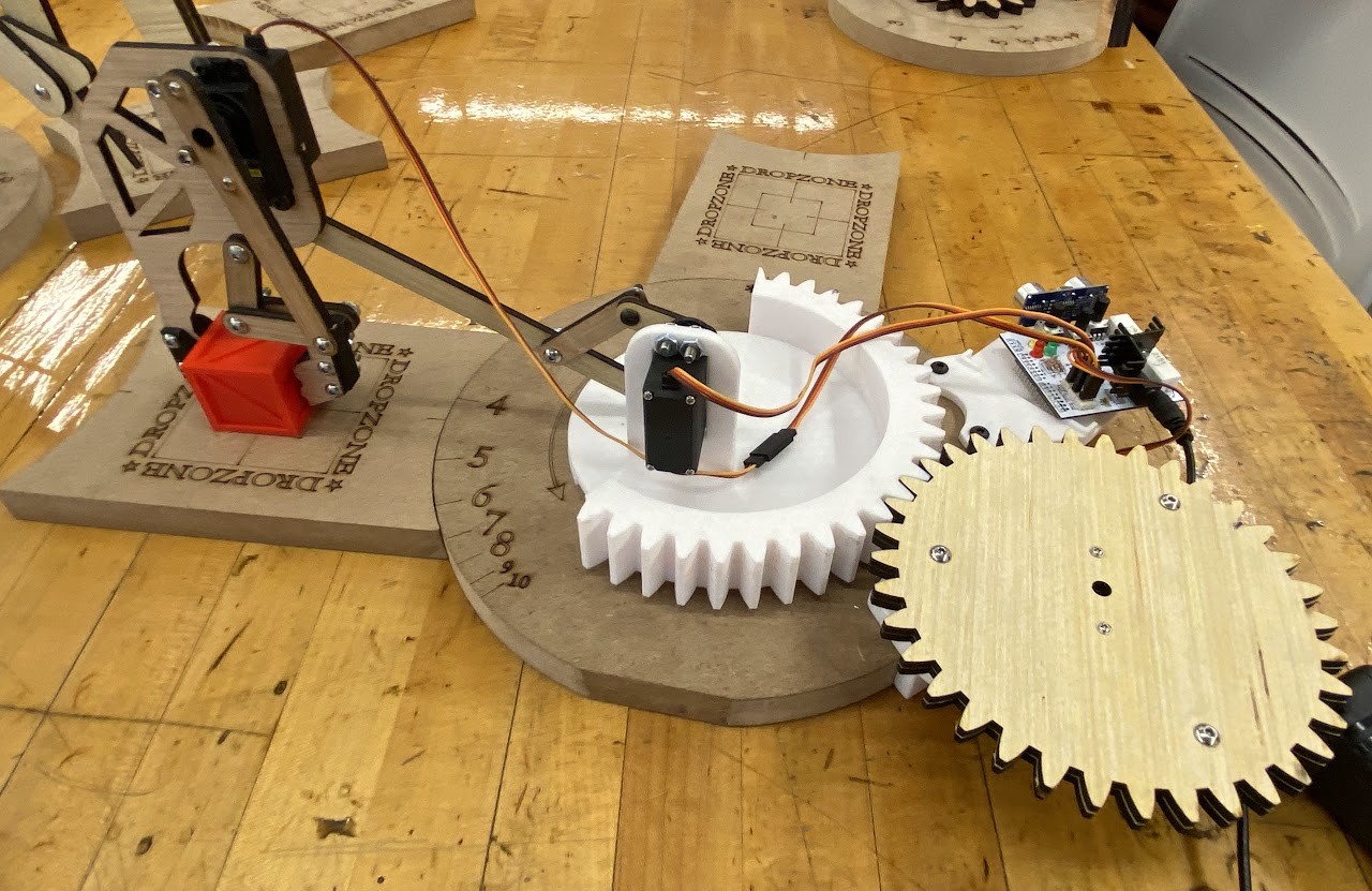
A bench-top pick-and-place mechanism built through four linked design phases—from the payload itself to a complete gripping, lifting, and rotating system.
Linkage synthesis
Arduino control
MATLAB analysis
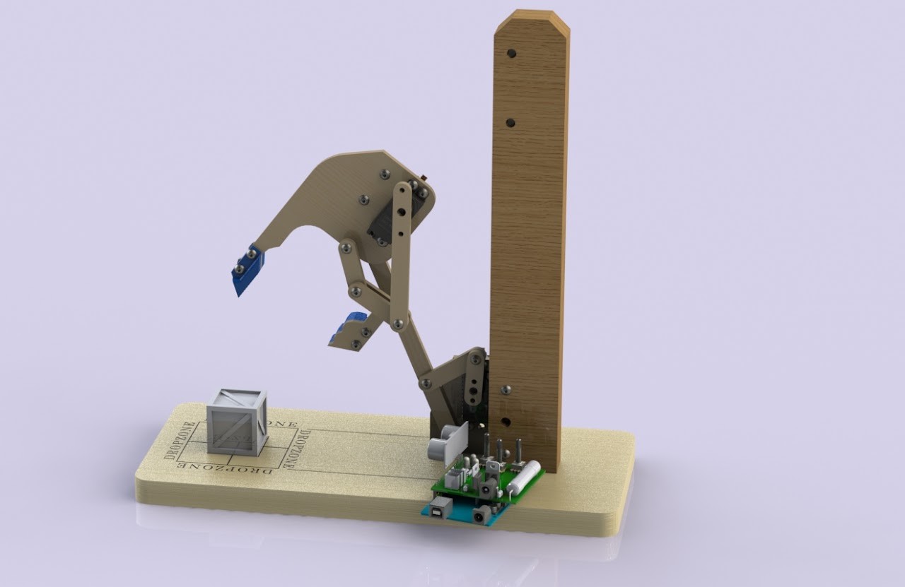
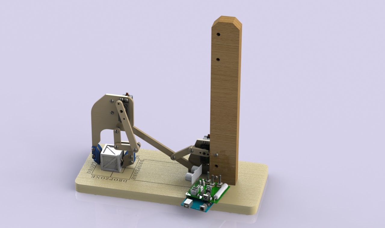
Full mechanism · CAD assembly
Team
Four students
My work
Concepts, Arduino, MATLAB & documentation
Design approach
Four progressive phases
Fabrication
Laser-cut plywood & 3D-printed parts
My contribution
Design ideas. Analysis. Control.
I contributed mechanical concepts throughout the project, wrote Arduino control code and MATLAB analysis, and created the team’s project website.
The team’s documentation specifically traces elements of my lifting-linkage concept and integrated rotating-base mounting concept into the selected designs. The completed arm was a collaborative build.
Team: James Lee, Paul Porreca, Jorge Valentin, and Andrew Mastro.
The development process
Four phases. One connected system.
01
Payload
Design the object before its handler.
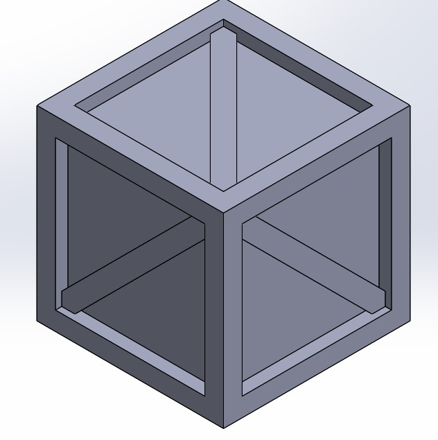
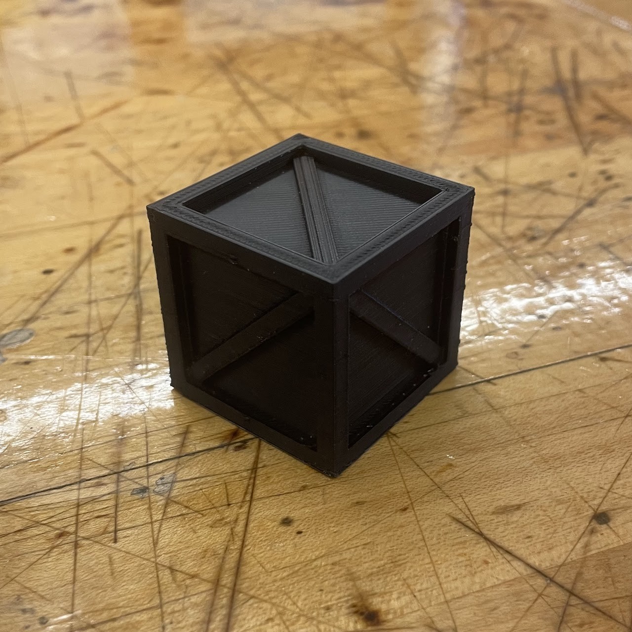
The object had to fit within a 1.5-inch cube, occupy at least one cubic inch, and be easy for a claw to grip. A decision matrix compared universality, stability, symmetry, and gripability.
Engineering details
Each teammate proposed a design. The team selected Andrew’s concept for its balance of stability and gripping access, then prepared it for fused-deposition 3D printing.
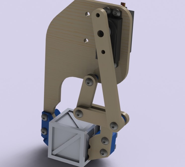
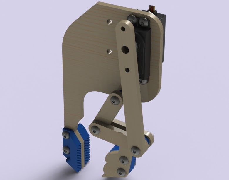
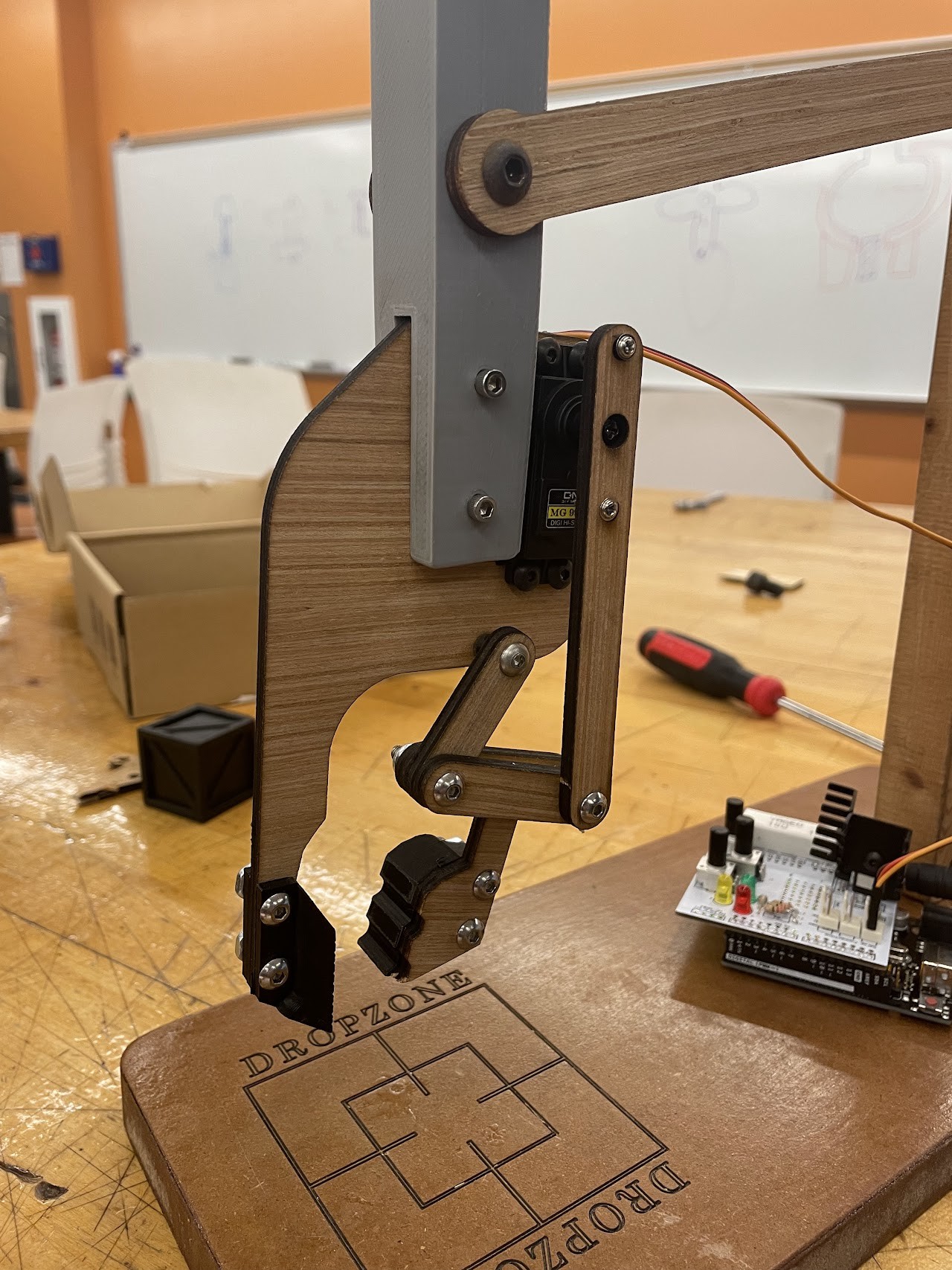
A servo-driven four-bar linkage opened and closed a plywood claw. The design balanced size, strength, mass, and range of motion while avoiding interference with the payload.
Engineering details
The team selected Paul’s compact concept and refined the jaw and linkage arrangement. Degree-of-freedom analysis and graphical linkage synthesis supported the design. Testing showed the gripper could pick up the team’s payload and the other teams’ payloads.
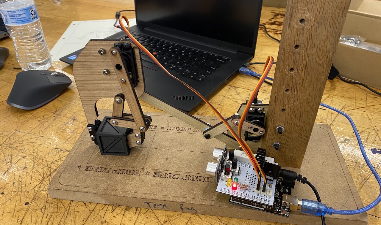
A second four-bar linkage lifted the gripper and payload using mechanical advantage. The selected concept combined aspects of my design and Paul’s, with the servo near the base and a lighter gripper connection.
Engineering details
The target lift was 1–3 inches, followed by a three-second hold and controlled return. Instant-center geometry and MATLAB analysis supported the mechanical-advantage evaluation. Sonar placement and motion speed required tuning during testing.
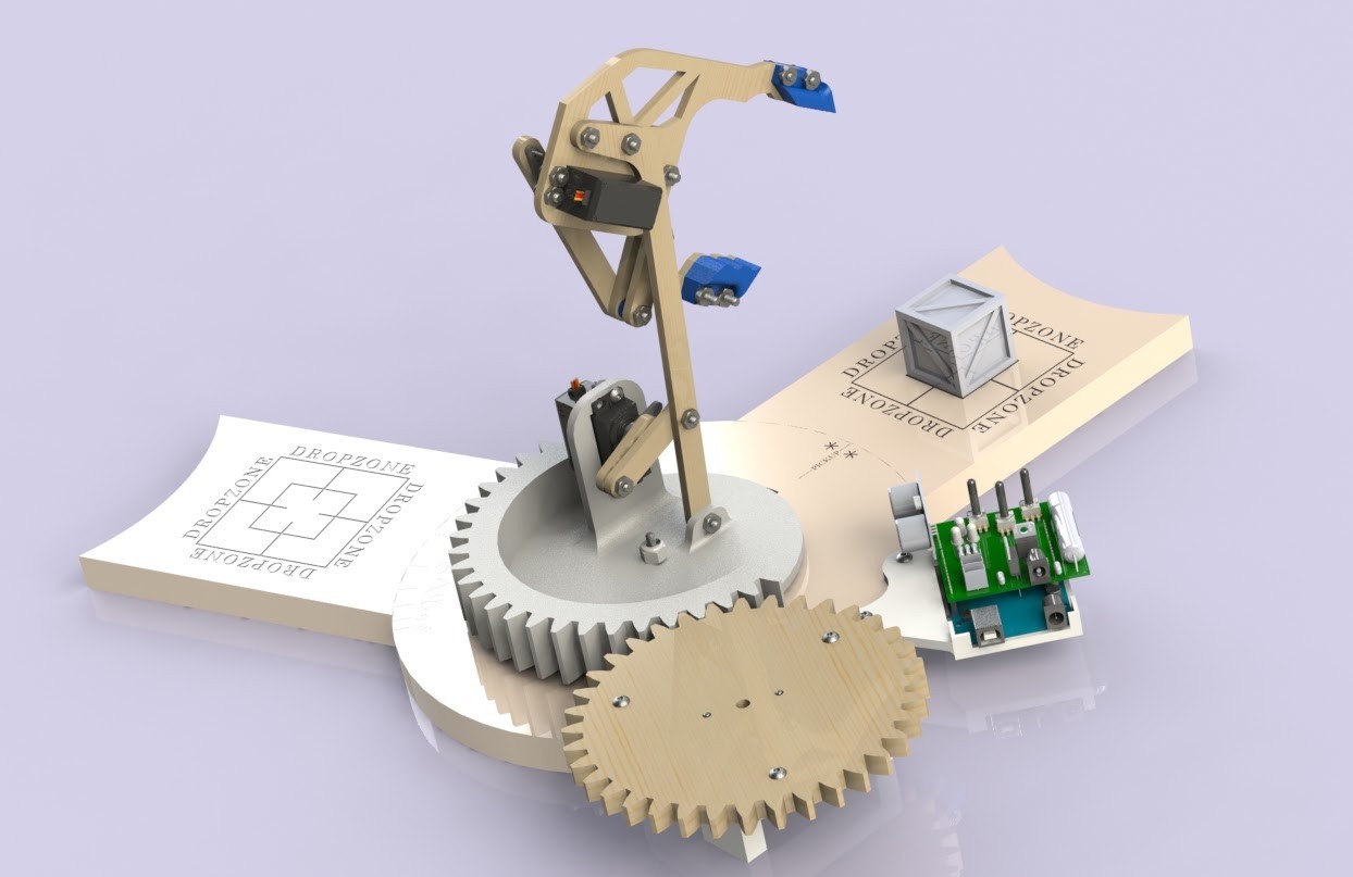
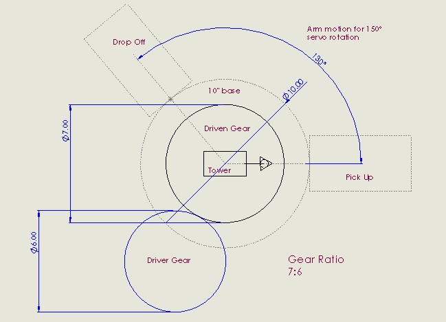
A third servo drove a geared base to move the arm between pickup and drop-off zones. The final concept combined Andrew’s under-mounted servo approach with an integrated printed gear/mount idea from my concept.
Engineering details
The source design used an approximately 7:6 angular ratio to translate about 150° of servo travel into the required base rotation. A partial driven gear reduced material and print time. Brackets and sliding supports were designed around assembly access and rigidity.
The lifting-stage reflection reports successful lifting of all seven class payloads after sensor positioning and speed tuning.
~1 cm
Drop-position offset
Final testing found a repeatable forward placement error, alongside successful transfers when the pickup payload was well aligned.
Fit
System-level lesson
The pickup window was too narrow to reliably accept off-center deliveries from neighboring arms. Gripper reach and alignment tolerance were the next improvements.
This project connected classroom mechanism analysis to physical behavior: actuator limits, sensor placement, motion timing, assembly rigidity, and tolerance between neighboring systems.