2025 IREC / SDL Payload Challenge
Lil Planty.
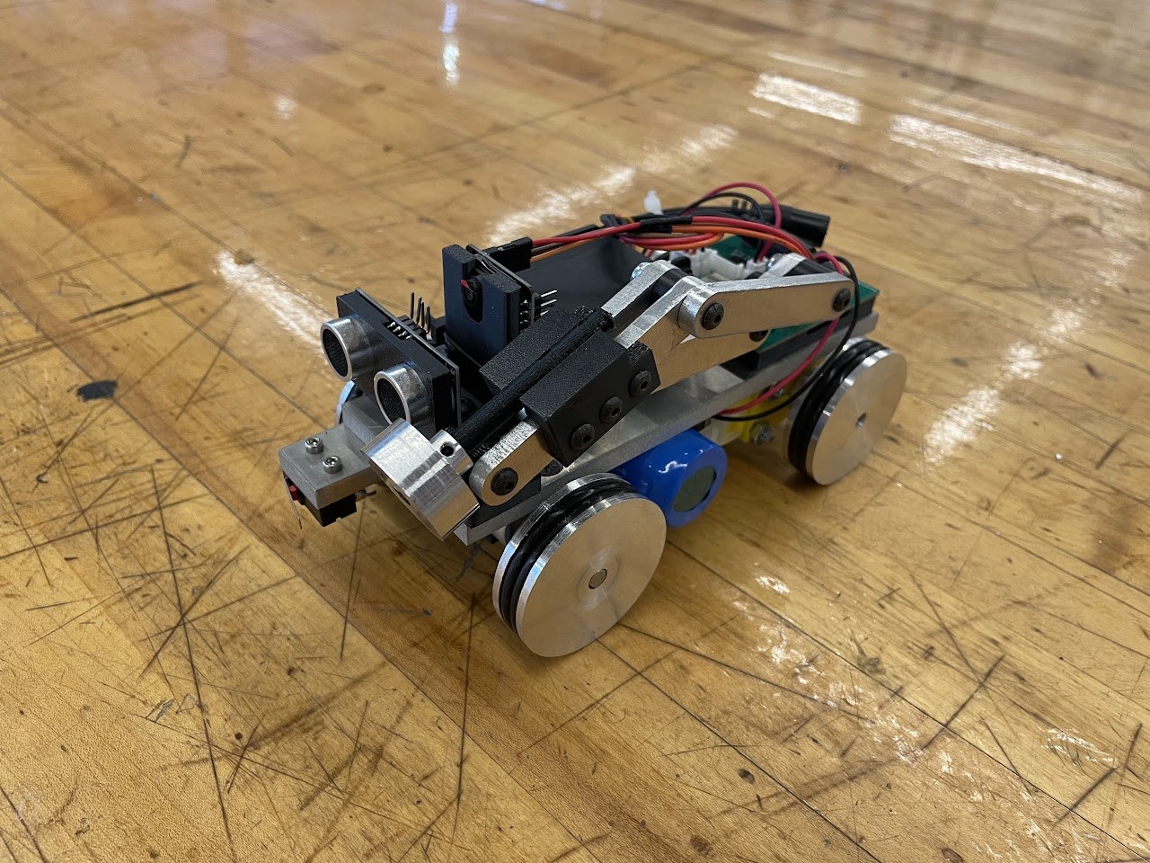
A small rover.
A complete engineering system.
An autonomous flag-planting rover designed to deploy after landing, exit its enclosure, and plant a flag—all within a 3U payload envelope.
Honorable Mention for Outstanding Craftsmanship
- My role
- Sole payload engineer
- Payload envelope
- 10 × 10 × 30 cm
- Outcome
- Flag-planting mission completed
- Competition
- IREC · Midland, Texas · 2025
01 / The challenge
One mission. Many interdependent parts.
Lil Planty was Rowan University's payload for the 2025 International Rocket Engineering Competition. Its mission was inspired by Apollo 11: deploy a rover and plant a small flag after landing.
I developed the payload independently, taking responsibility for its mechanical design, electronics, programming, fabrication, and integration. The challenge was to make each subsystem work within the same compact envelope—and make them work together.
The engineering constraints
- Package the rover, mechanisms, and electronics within a 10 × 10 × 30 cm envelope.
- Integrate the payload with the rocket's mounting and recovery arrangement.
- Allow access for assembly, wiring, modification, and maintenance.
- Choose fabrication methods and materials that could be produced with available equipment.
02 / Mechanical development
Designing for the shop, not just the screen.
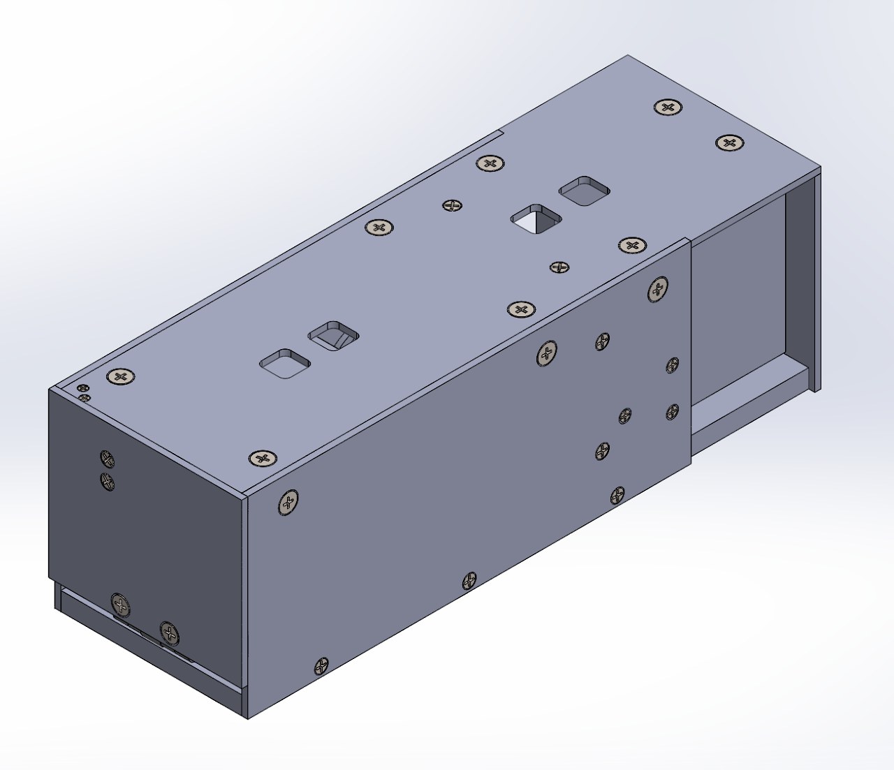
The enclosure evolved through three approaches. Each iteration addressed a practical limitation of the previous concept.
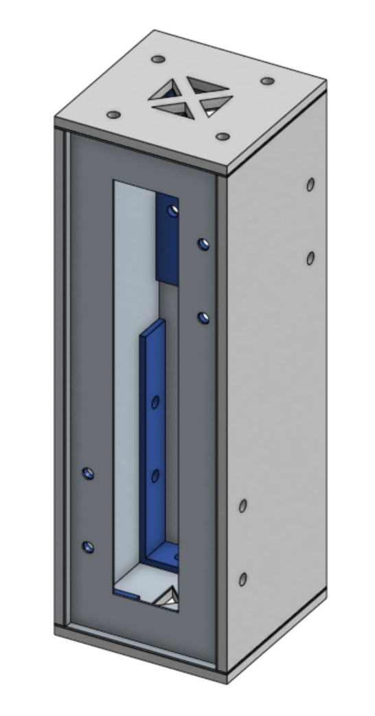
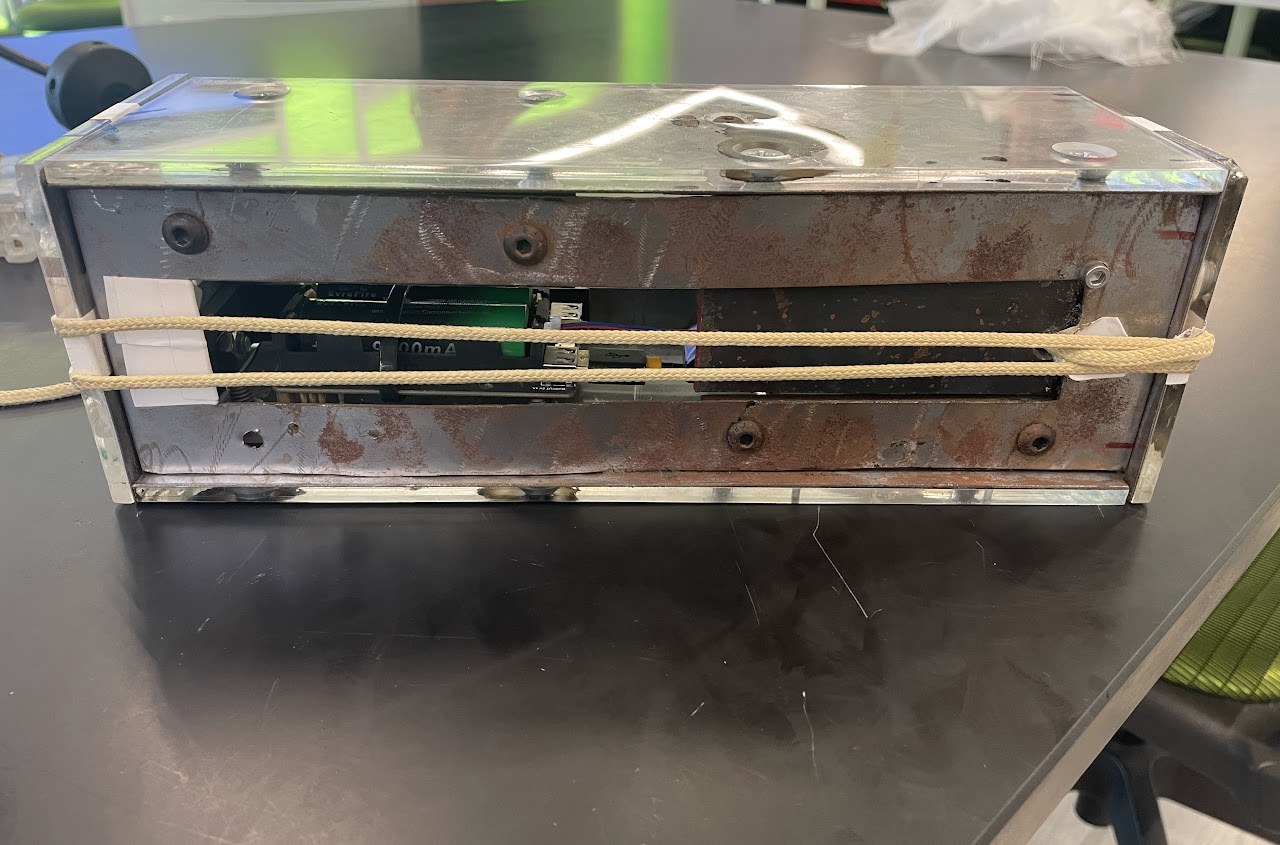
First: understand the existing design
I began by reverse engineering the previous year's payload structure in CAD. Its mission was different, and its acrylic exterior presented a concern about brittleness. The new rover mission required a structure designed specifically around deployment and internal access.
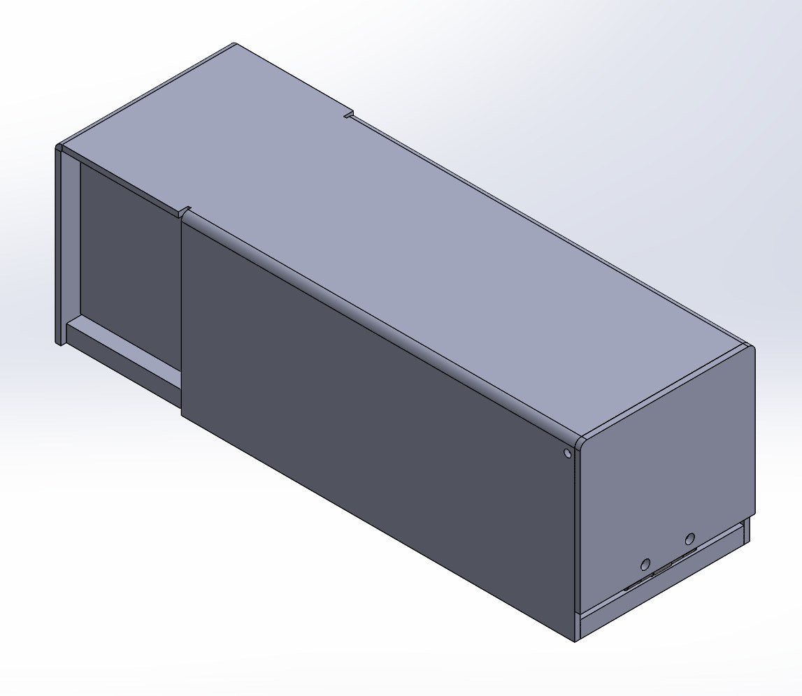
Then: evaluate a bent shroud
The next concept combined a substantial base with a removable metal shroud. The base was intended to lower the center of gravity and provide mounting points. The shroud would offer convenient disassembly, but the planned 1/8-inch 6061 aluminum created manufacturing challenges.
- A suitable press brake was not immediately available.
- The flat profile exceeded the available waterjet bed size.
- Adding access holes after bending would be difficult.
- Maintaining the specified 2 mm dimensional tolerance was uncertain.
Finally: make the panels modular
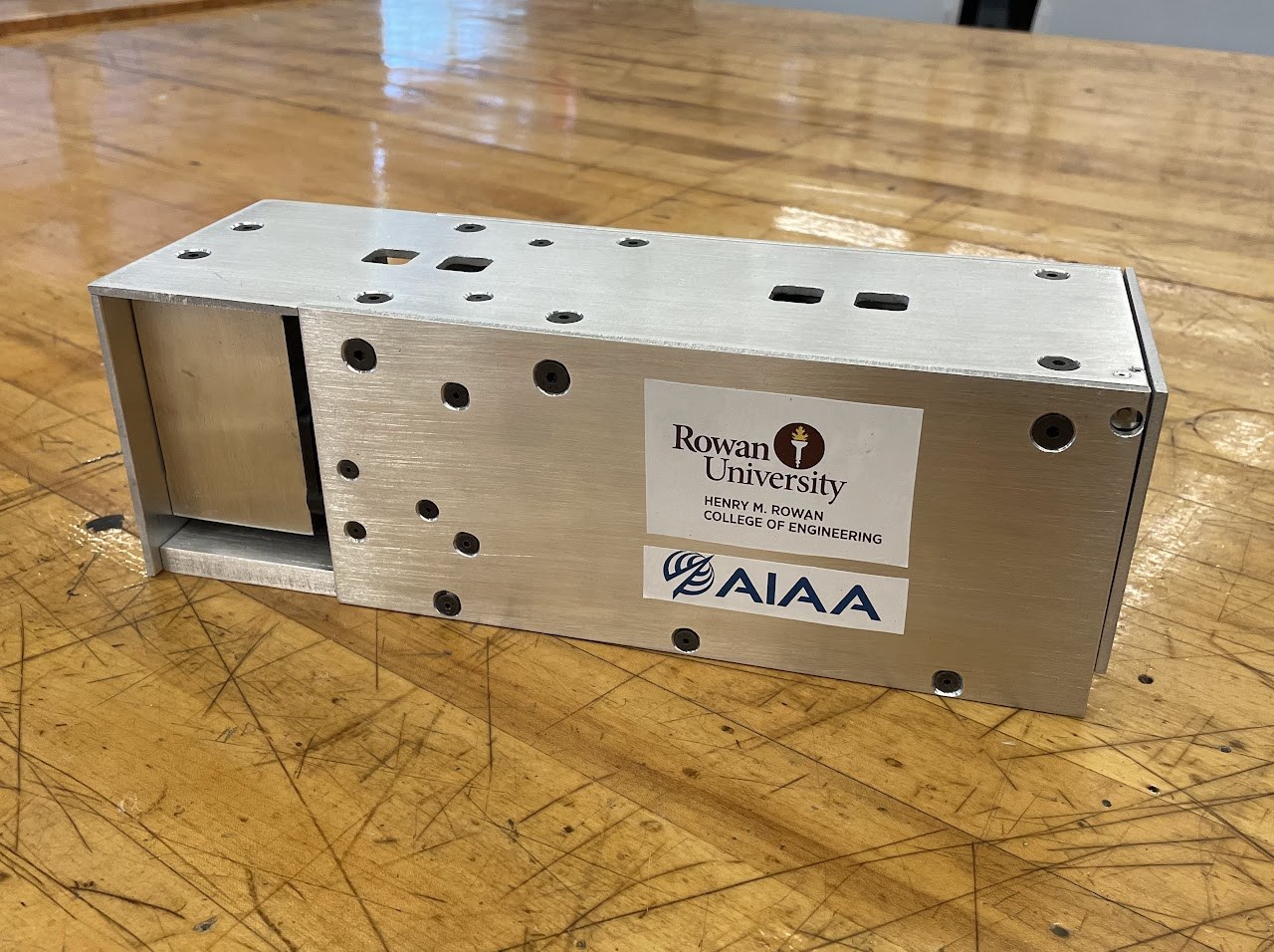
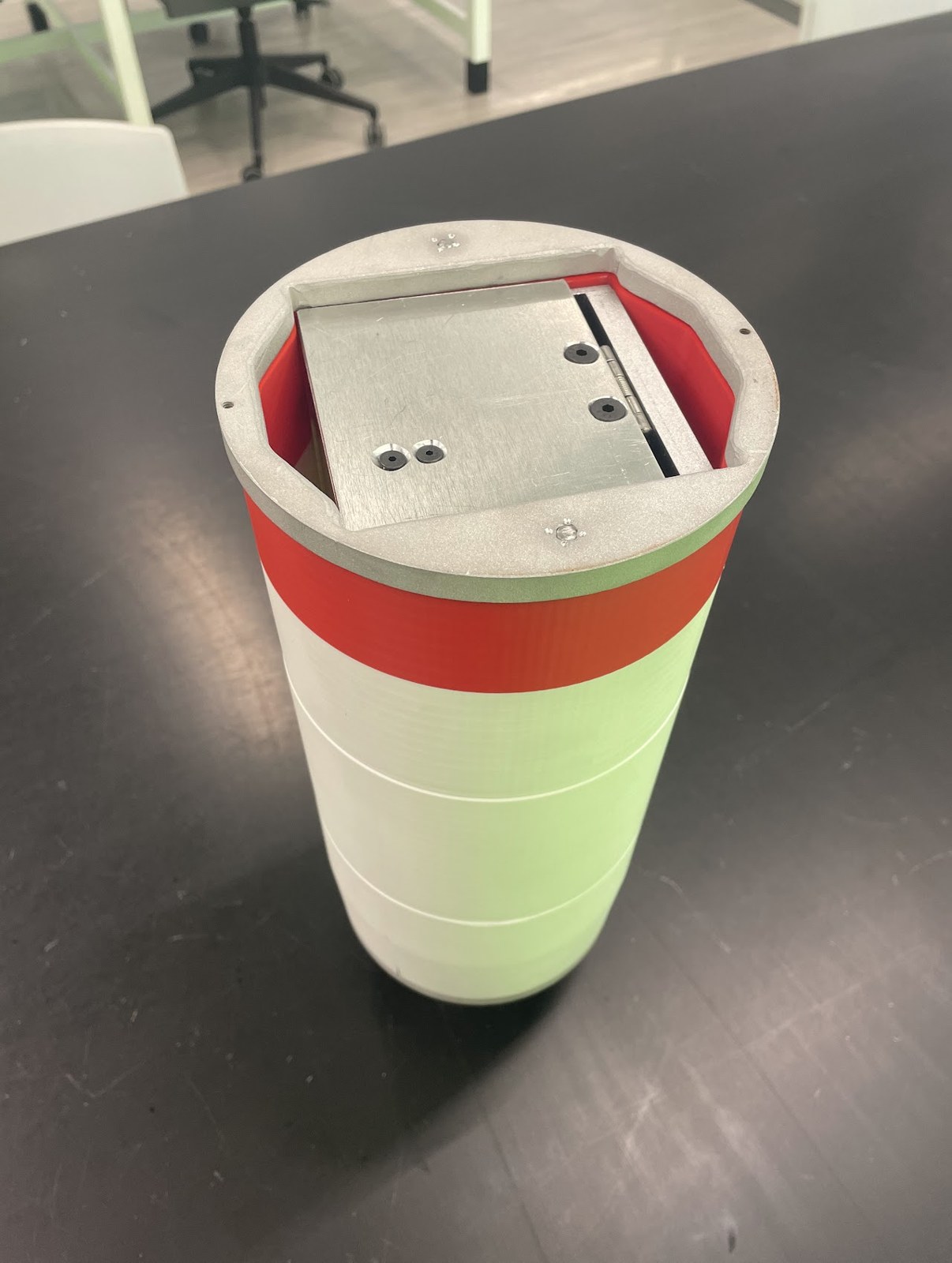
Individual waterjet-cut panels could be screwed together, removed, and modified separately. This made the enclosure more practical to manufacture and increased confidence in controlling its dimensions.
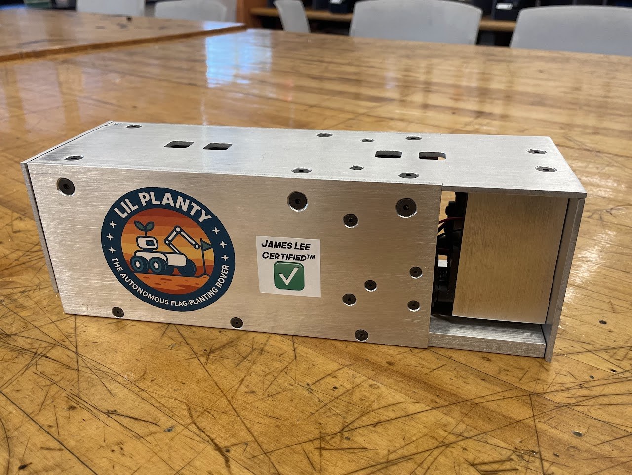
A manufacturable, serviceable assembly was more useful than an elegant concept that depended on unavailable equipment.
03 / Electronics & control
From Arduino prototypes to custom PCBs.
Custom circuit-board development was one of the biggest learning challenges of the project. It extended well beyond what I had been taught in mechanical engineering.
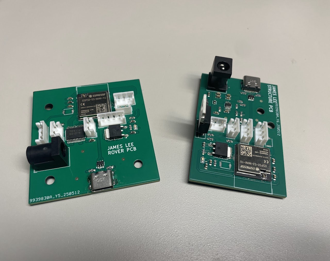
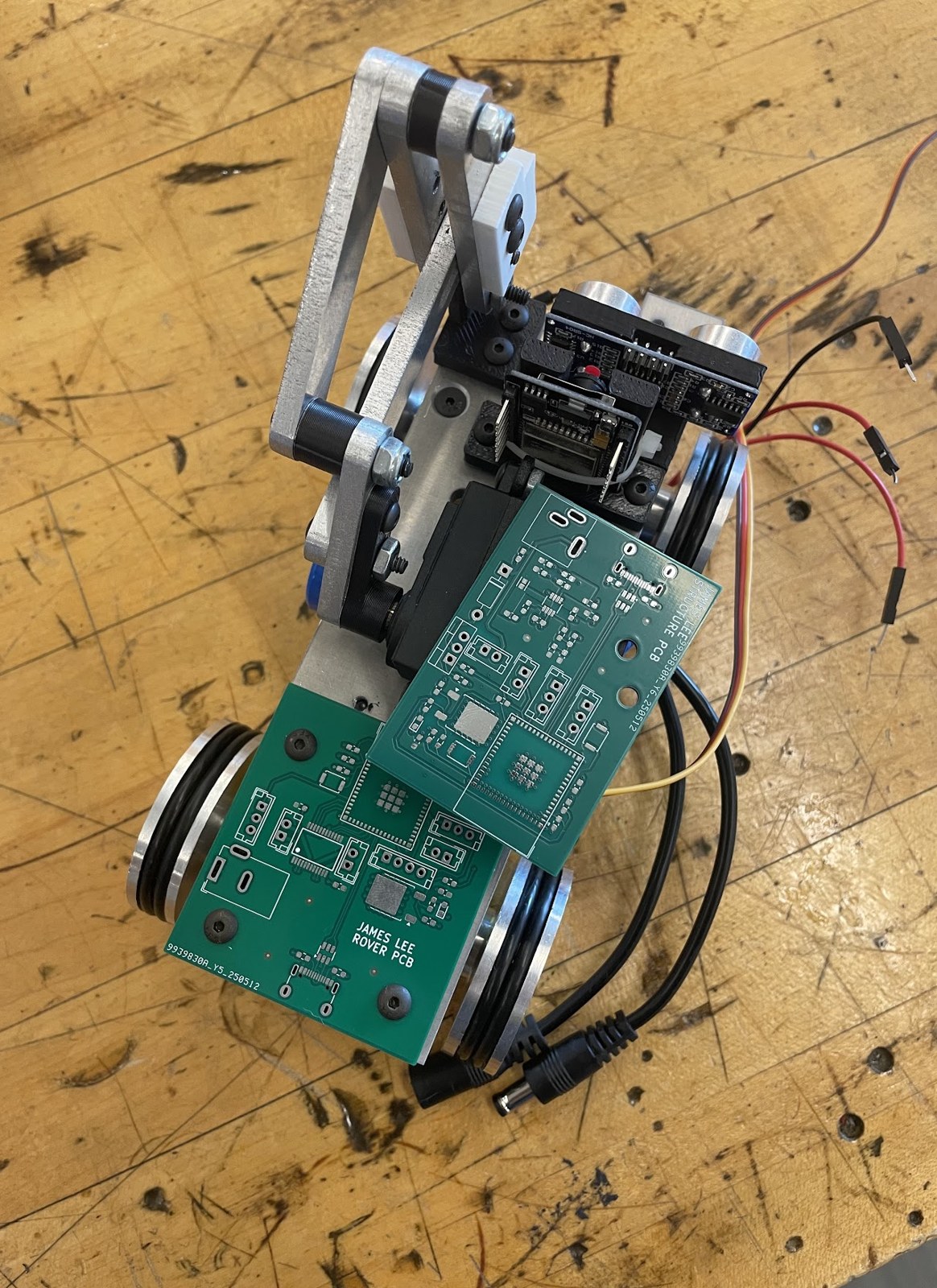
Initial prototypes used Arduino boards because they were familiar and convenient for developing the logic. The final product used custom PCBs: one on the rover and another within the enclosure, each supporting the electromechanical operations of its subsystem.
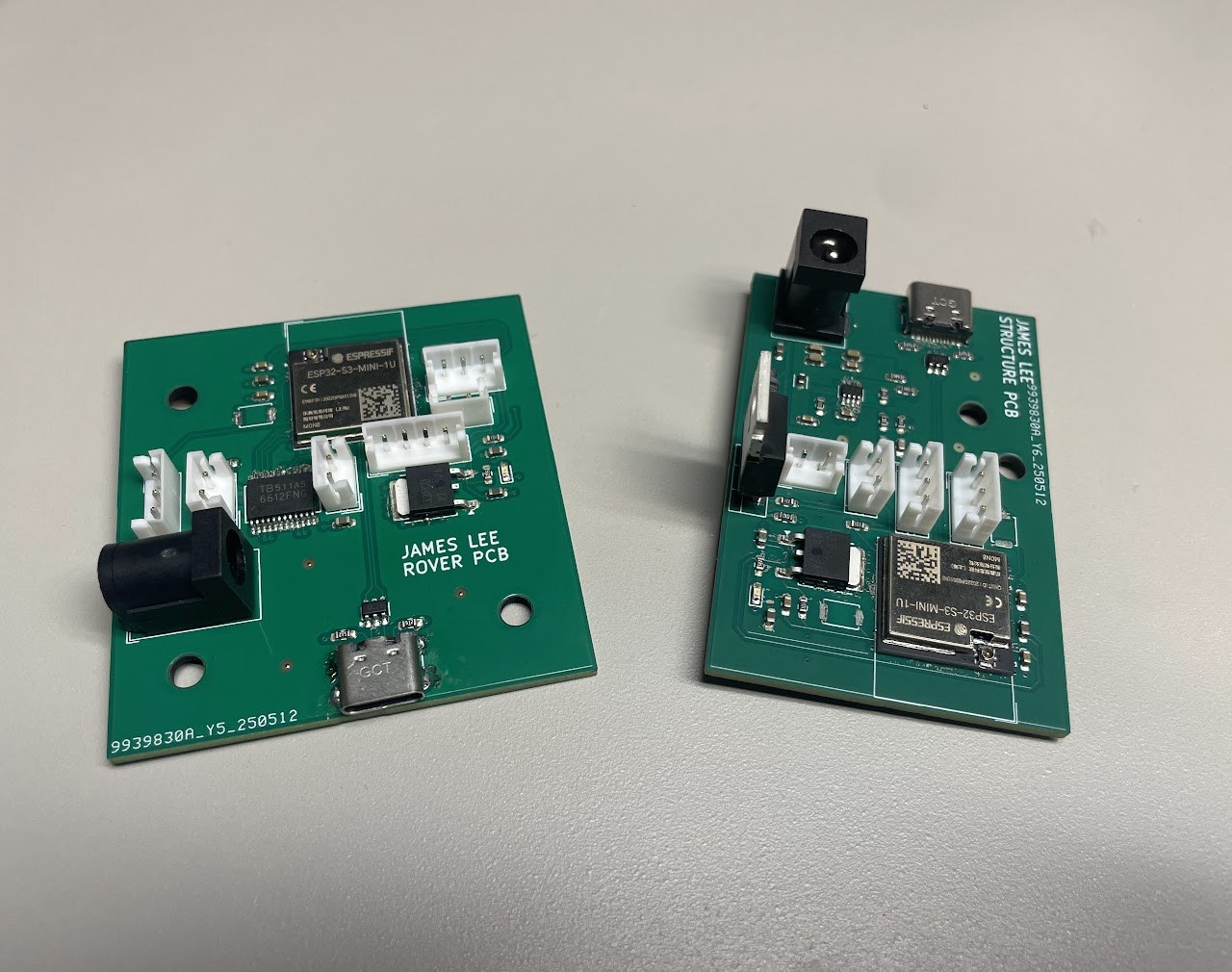
Developing the electronics as part of the system
The transition to custom boards was intended to reduce packaging demands and simplify wiring. The work included schematics, board layout, component selection, fabrication, and physical integration with the mechanical assemblies.
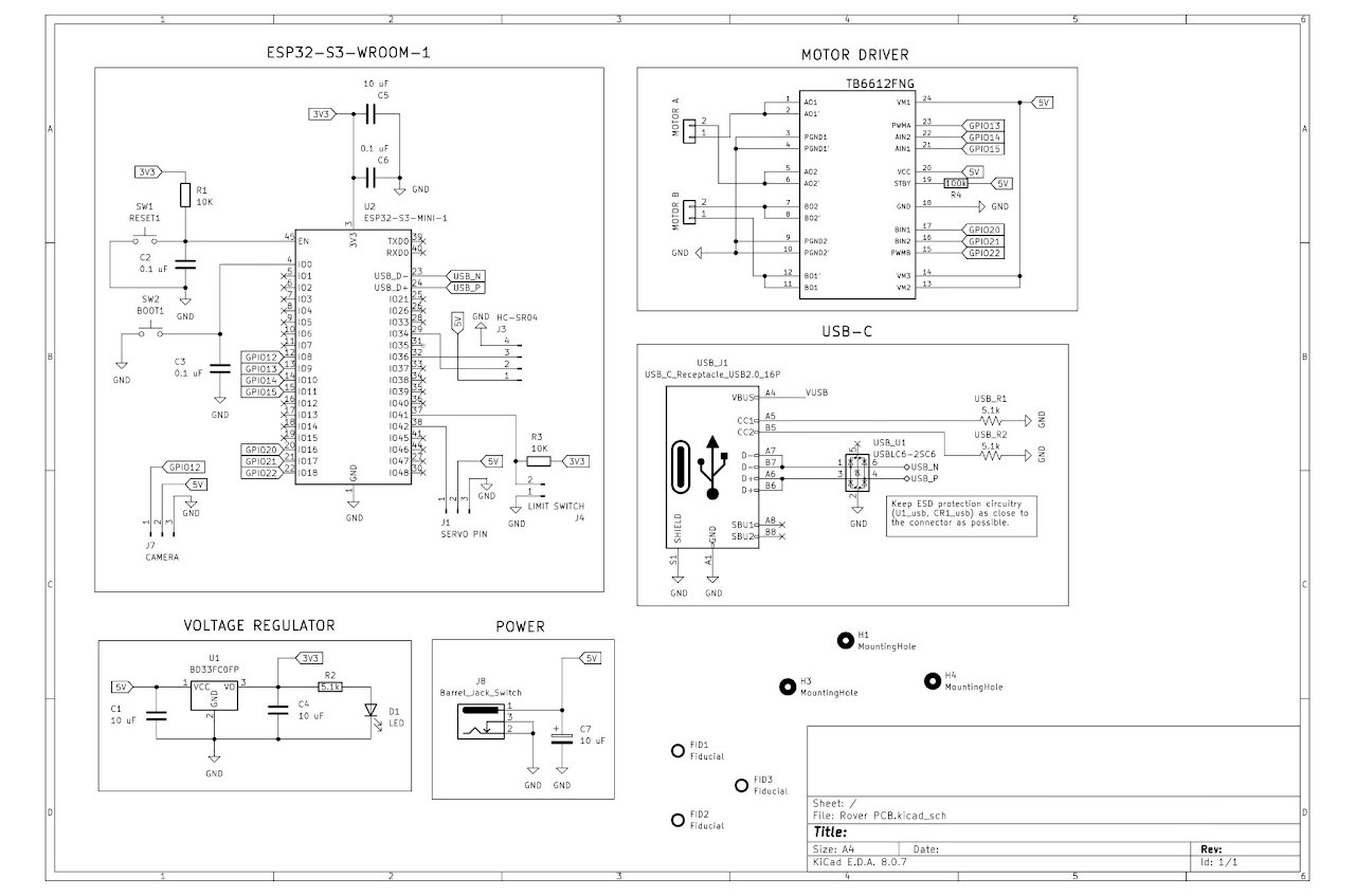
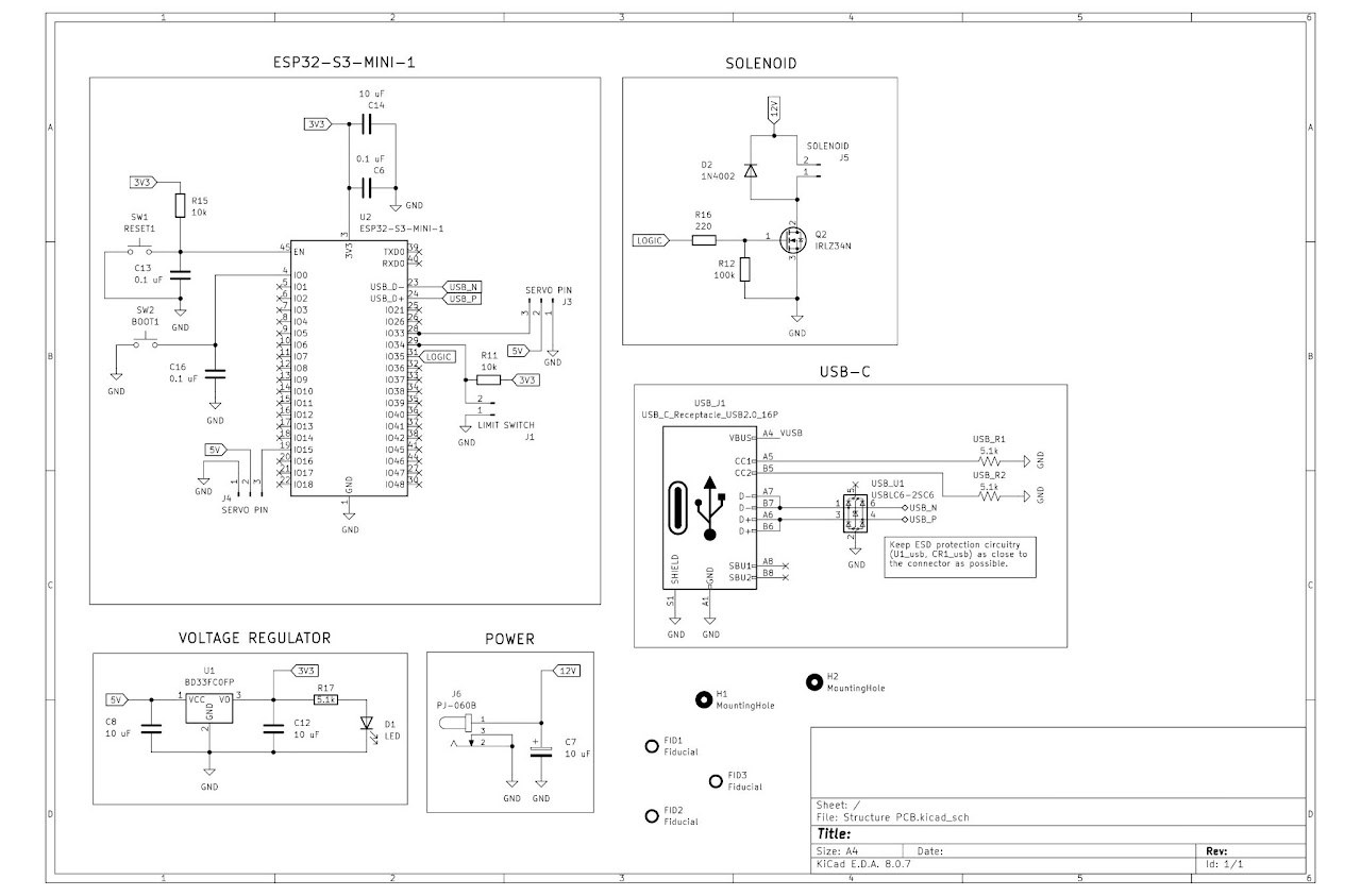
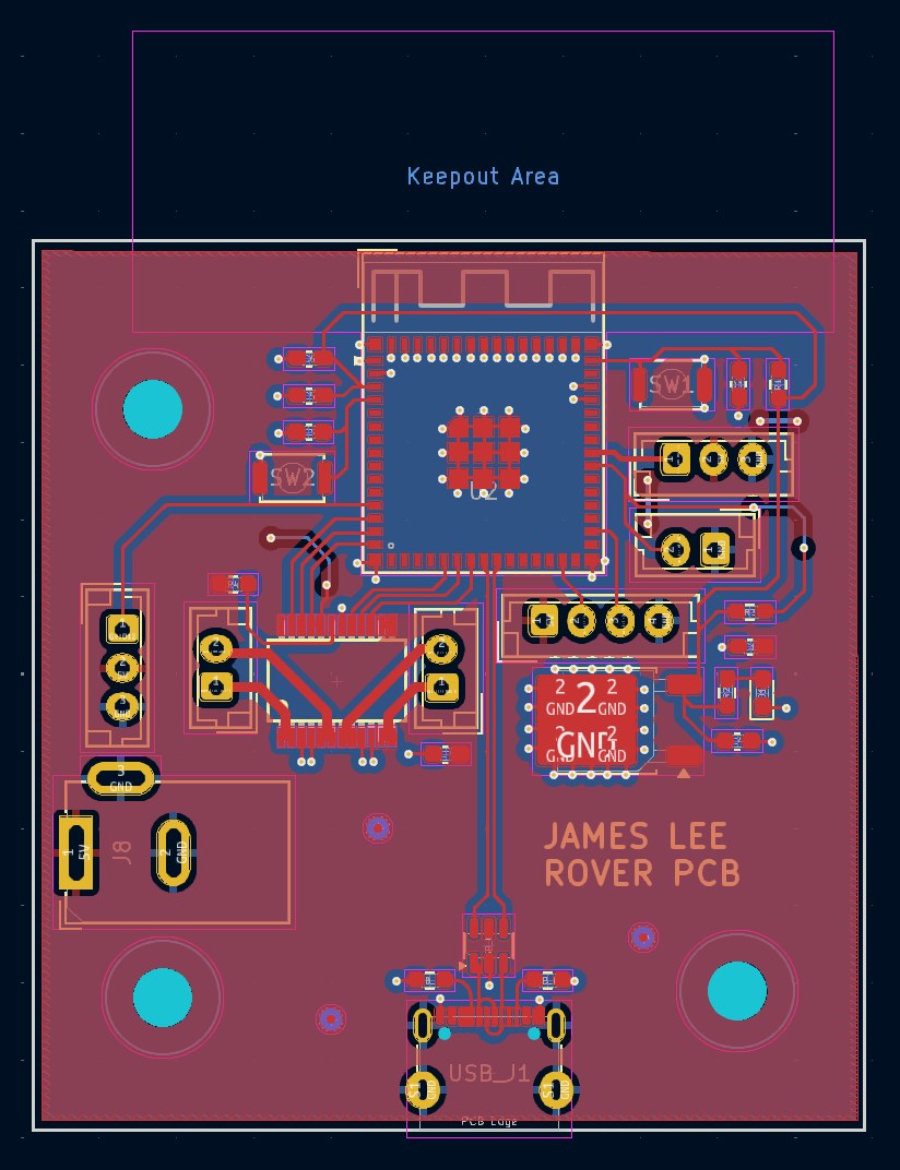
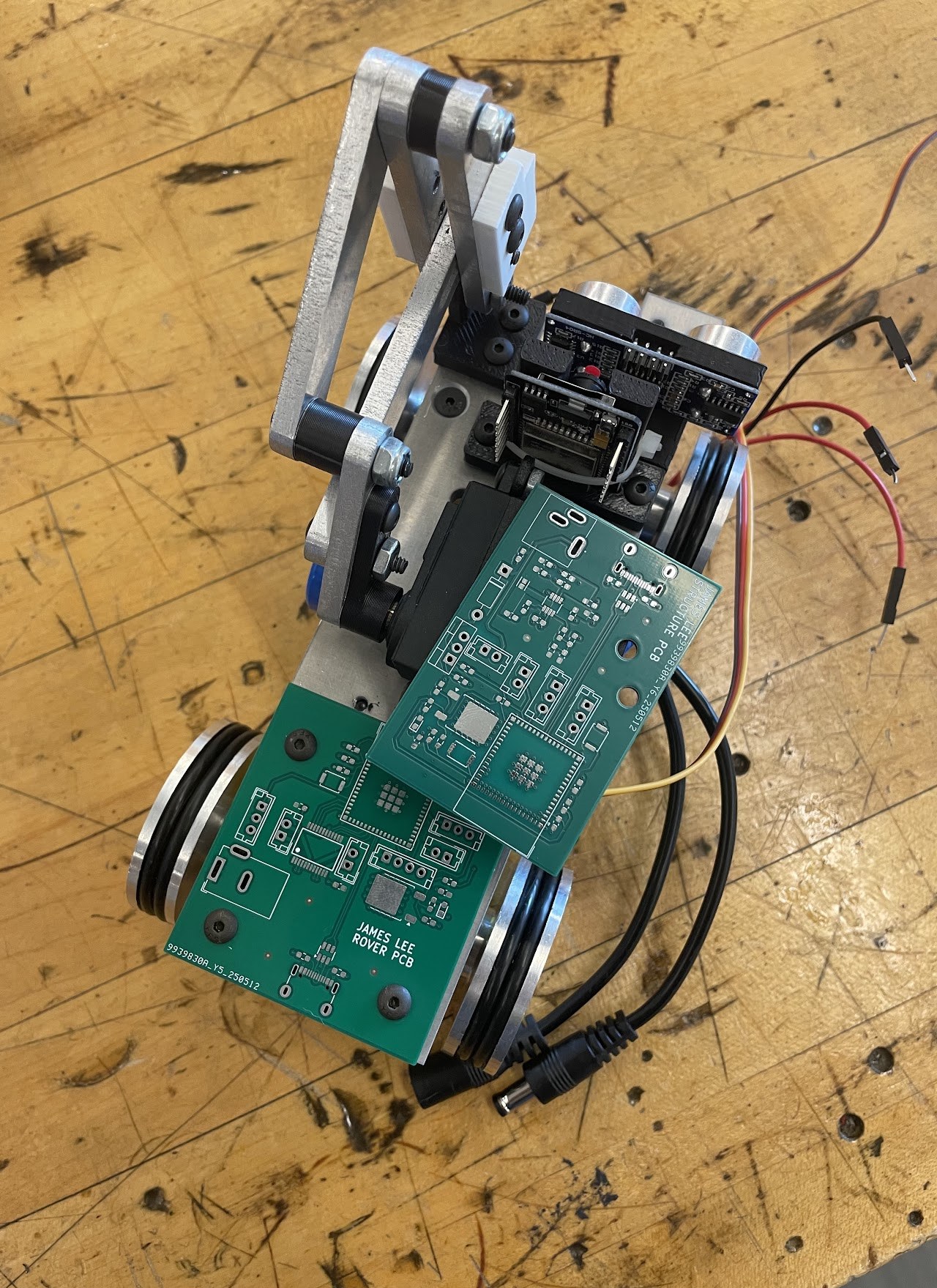
Electronics could not be treated as a separate package added at the end. Board size, wiring, component access, and mechanical motion all influenced one another.
04 / Electromechanical mechanisms
Turning commands into motion.
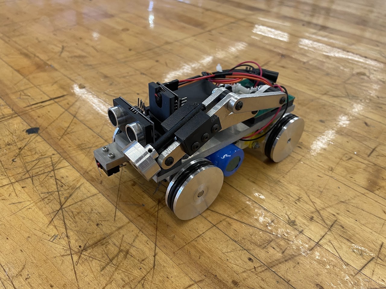
The rover
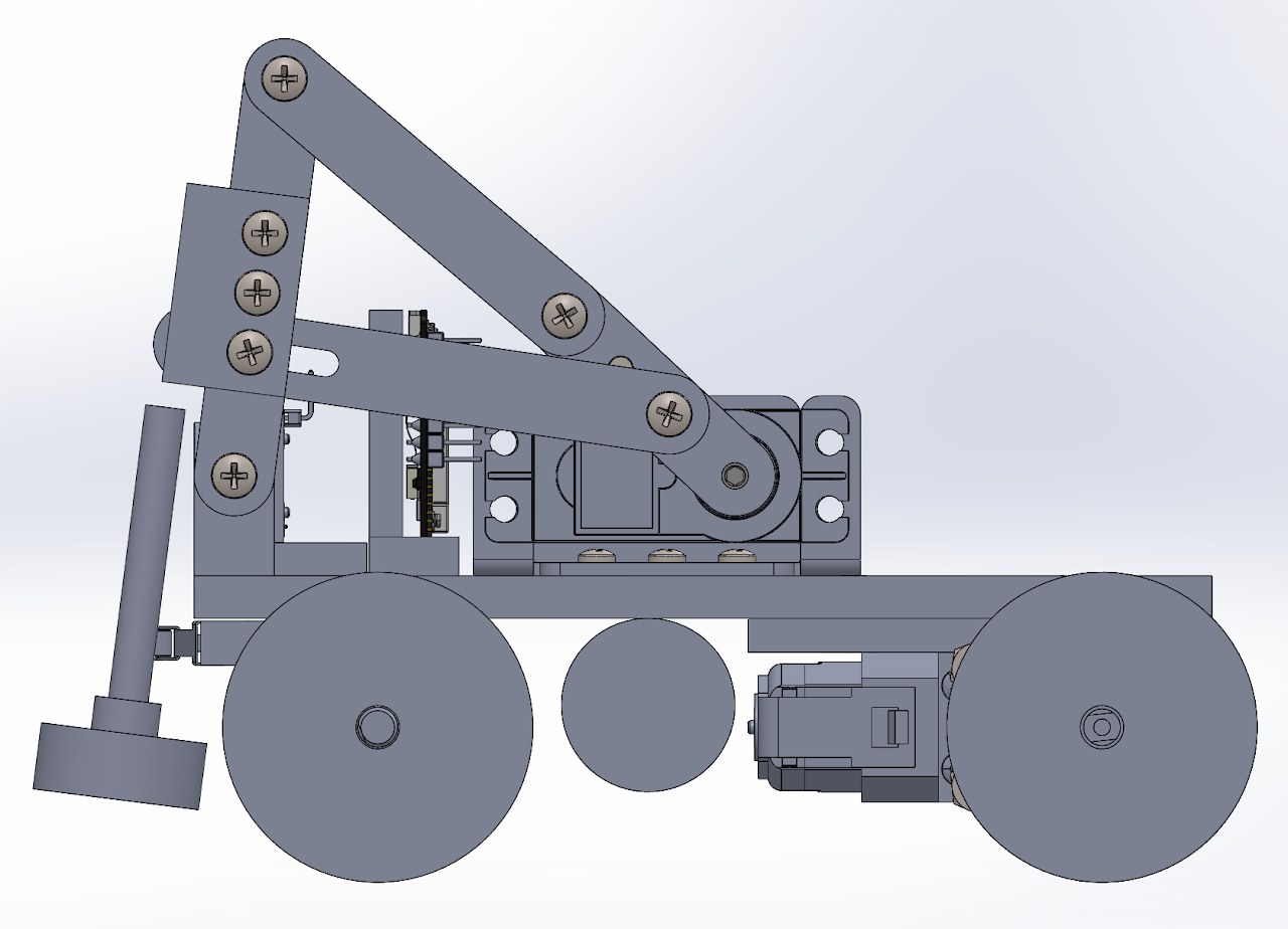
The rover progressed from early electrical prototypes to a fabricated assembly with its own control electronics and flag-planting mechanism.
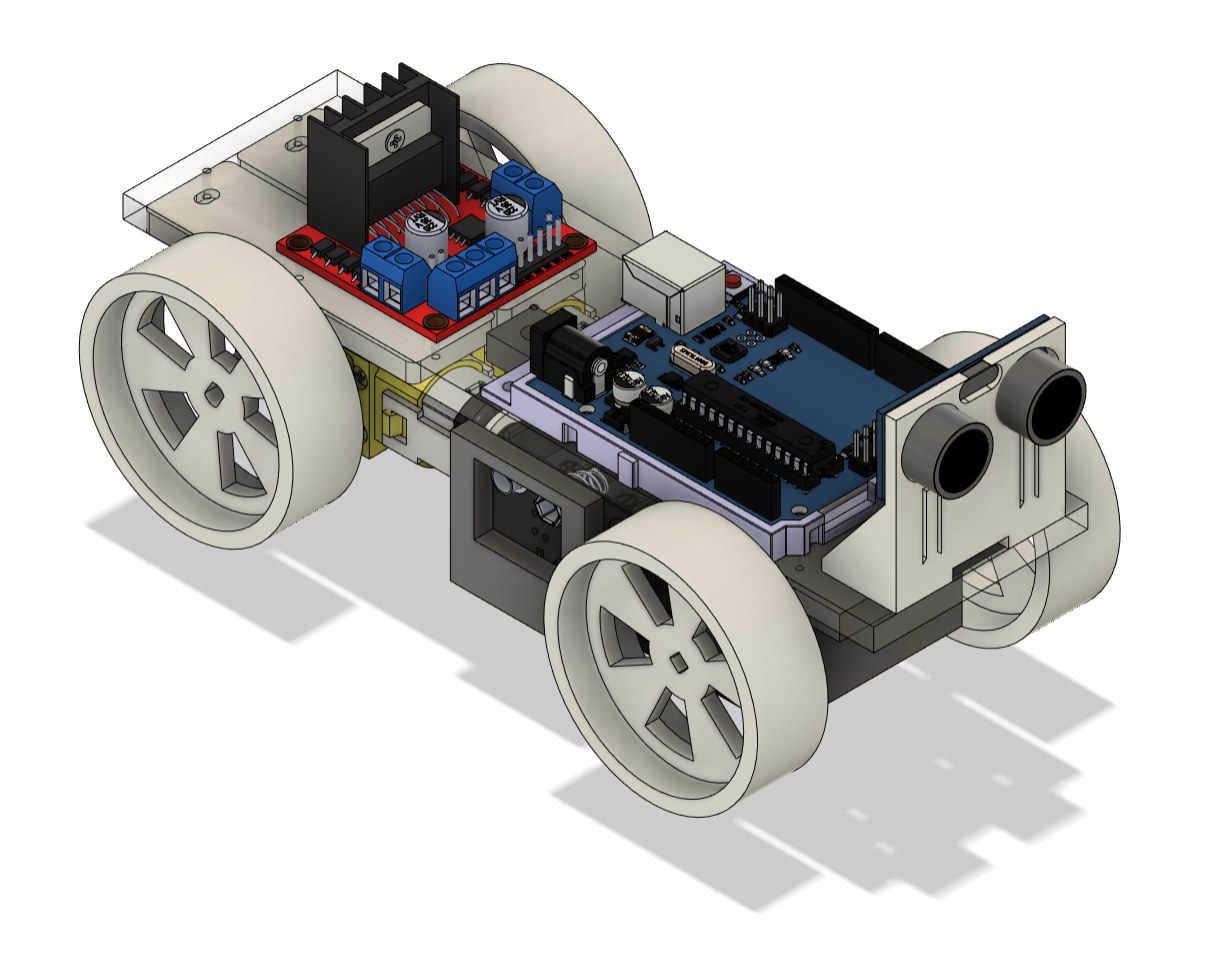
Flag-planting mechanism
A servo-powered arm and four-bar linkage provided the mechanical motion for the flag-planting task. The mechanism had to operate while remaining compatible with the rover's compact packaging.
Door release and landing flaps
The enclosure included a solenoid latch and spring-loaded landing gear. The original project documentation includes a latch prototype demonstration and a preliminary rack-and-pinion landing-flap concept. These mechanisms were part of the larger deployment sequence.
Latch development ↗Landing-flap development ↗Latch prototype video ↗
05 / Rocket integration
A payload designed to fit its vehicle.
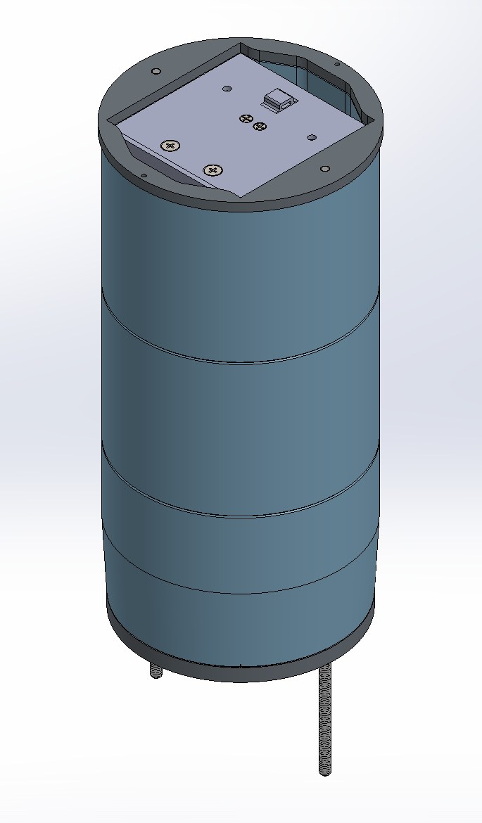
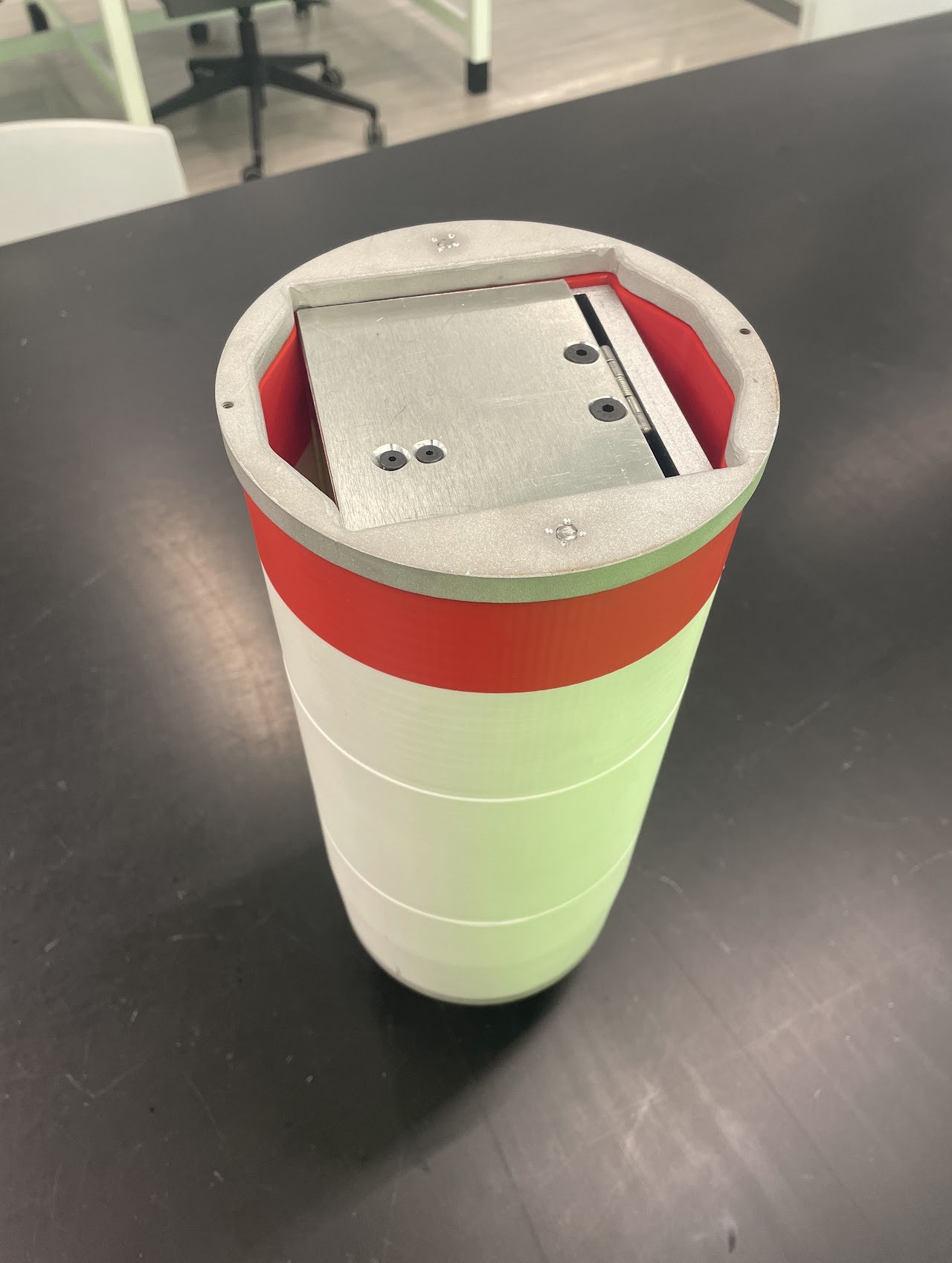
The rocket interface needed to hold the payload securely during launch while allowing it to slide out during recovery separation and remain tethered. The mount was designed around the nose-cone coupler and the payload enclosure.
Prove the fit before committing to the final material
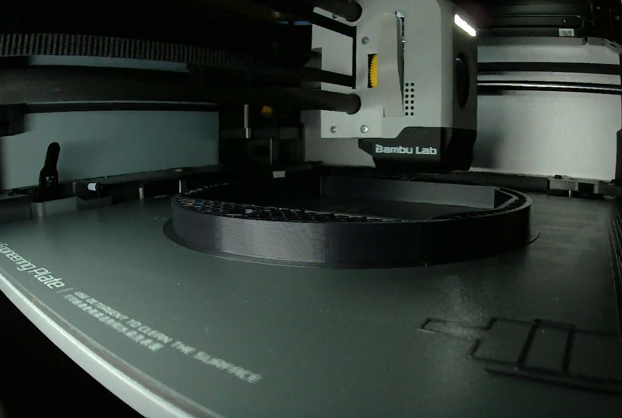
The mount used three printed modules, with internal clearance for the payload and stored shock cord. Threaded rods connected the assembly, and aluminum plates completed the mounting arrangement.
A PLA prototype provided an inexpensive fit check. Testing showed that the enclosure could slide in and out without being excessively loose. The final mount was printed in ASA to better address the expected heat and UV exposure in Texas.
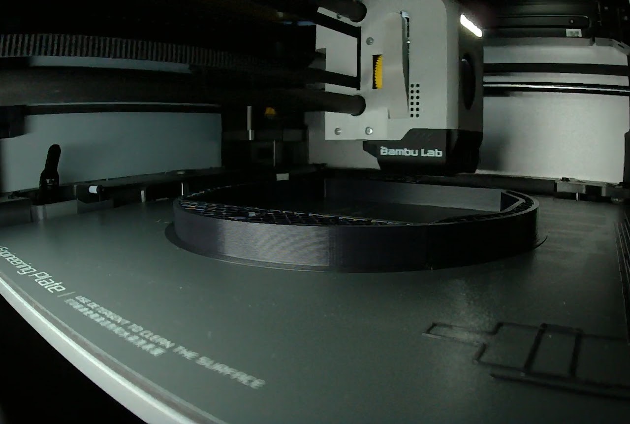
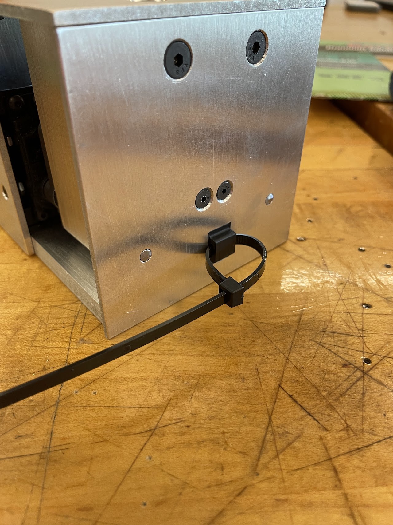
Separate fit validation from final-material fabrication. An inexpensive prototype can resolve integration problems before a more demanding print.
06 / Results & reflection
A completed mission. A new set of skills.
Mission outcome
Flag planted.
The rover completed its flag-planting mission.
Recognition
Outstanding Craftsmanship
Honorable Mention in the SDL Payload Challenge at the 2025 IREC competition.
Developing Lil Planty strengthened my experience in CAD, machining, fabrication, electronics, programming, and systems integration. The most important challenge was managing the relationships between subsystems while delivering a working physical product.
What I took from the project
- Design around fabrication: available tools and assembly access belong in the requirements.
- Prototype uncertain interfaces early: fit checks and mechanism prototypes reduce integration surprises.
- Learn across disciplines: custom PCBs became a central part of a project that began with a mechanical engineering background.
- Evaluate the complete sequence: individual components have to work together to accomplish the mission.
07 / Hardware gallery
From models to the workbench.
Selected CAD and hardware photographs from the project. Select an image to view it at full size.
Further documentation
The original development record.
The Google Site contains the original subsystem pages, additional media, and linked bills of materials.
Visit the Lil Planty project archive ↗← Back to all projects