Fabrication
CNC formwork
Prepare repeatable geometry and assemblies before they reach the site.
Tri-State Construction / Assistant project manager / 2021–2025
CNC formwork, concrete BIM, and in-house rebar detailing.
Turning design information into the models, drawings, and fabricated components that crews could use to build commercial concrete structures.
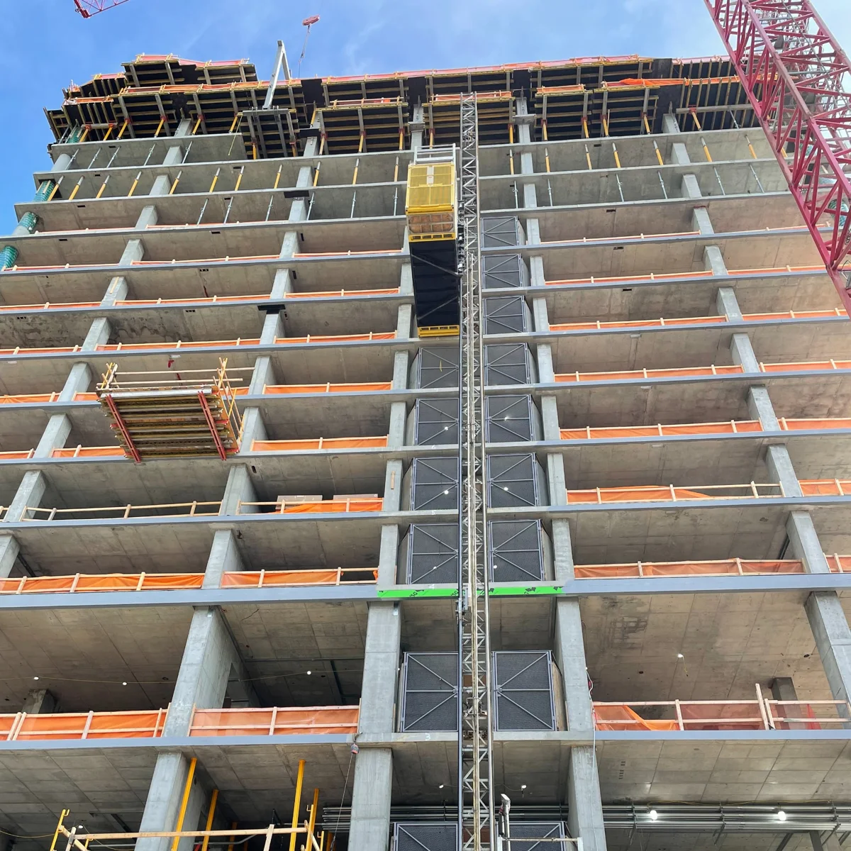
The context
At a union concrete subcontractor specializing in cast-in-place commercial construction, my work grew from CNC fabrication into concrete modeling and then rebar detailing.
Each stage addressed the same practical challenge: making complex design information useful to the people assembling, laying out, reinforcing, and pouring the concrete. I worked on physical formwork in the shop, digital foundation models in Tekla, and drawings that connected those models to field installation.
Fabrication
Prepare repeatable geometry and assemblies before they reach the site.
Coordination
Translate architectural and structural drawings into usable models and layout information.
Process development
Connect placement drawings, bend schedules, identification tags, and shop fabrication.
CNC formwork
I began by using a CNC router to make custom plywood formwork, including slab cutouts, slab edges, curved geometry, and other complex shapes.
Some components were difficult to reproduce efficiently by hand in the field. Preparing them in the shop gave the carpenters a defined set of pieces to work with. I sometimes assembled the formwork myself before it was palletized, shrink-wrapped, and shipped to the job site.
The work required thinking beyond a cut profile: how the plywood and bracing would fit together, how repeated parts would be organized, and how the finished assembly would be transported and used.
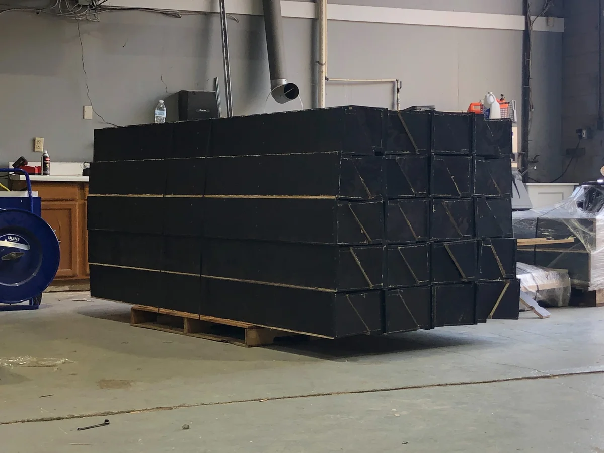
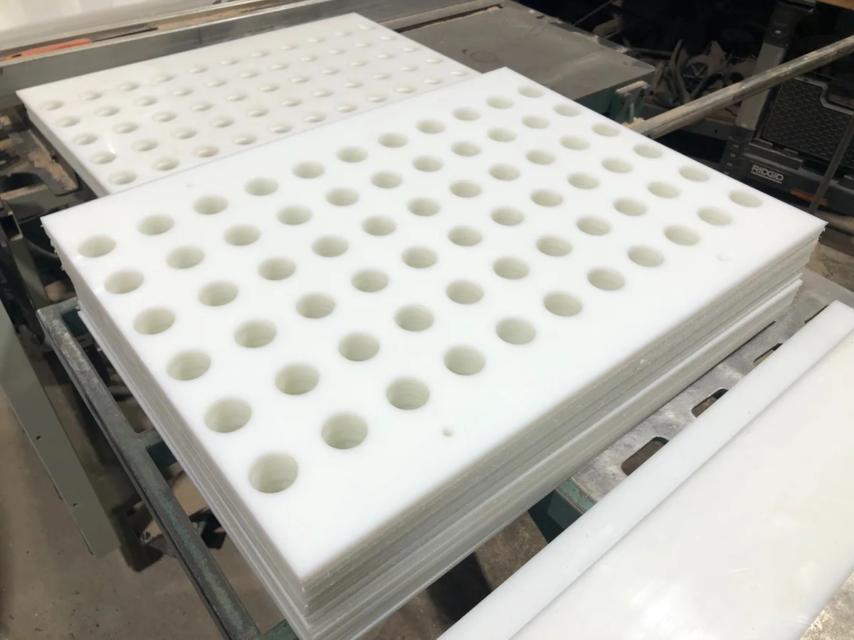
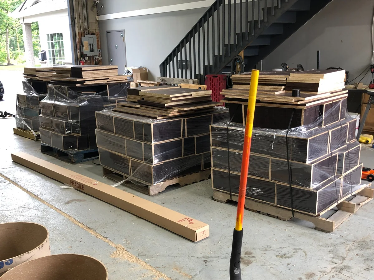
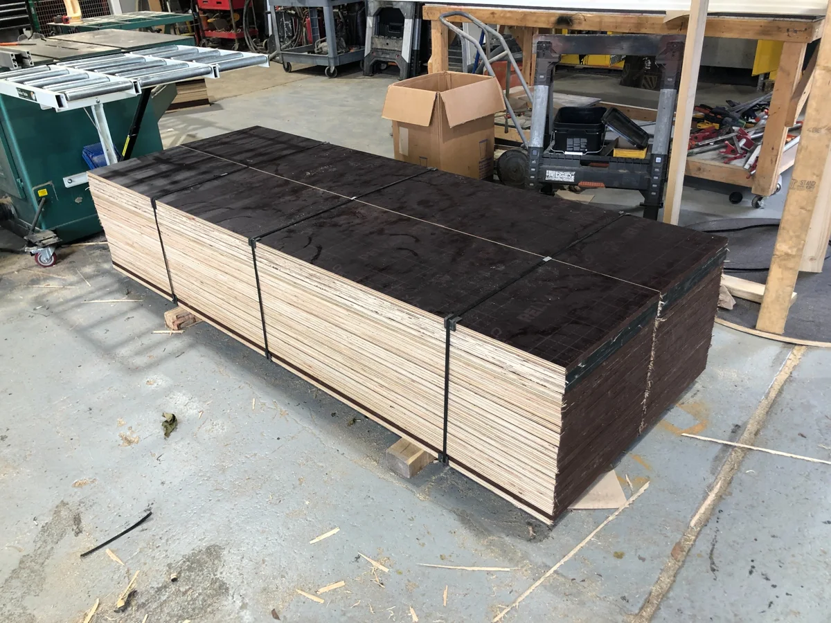
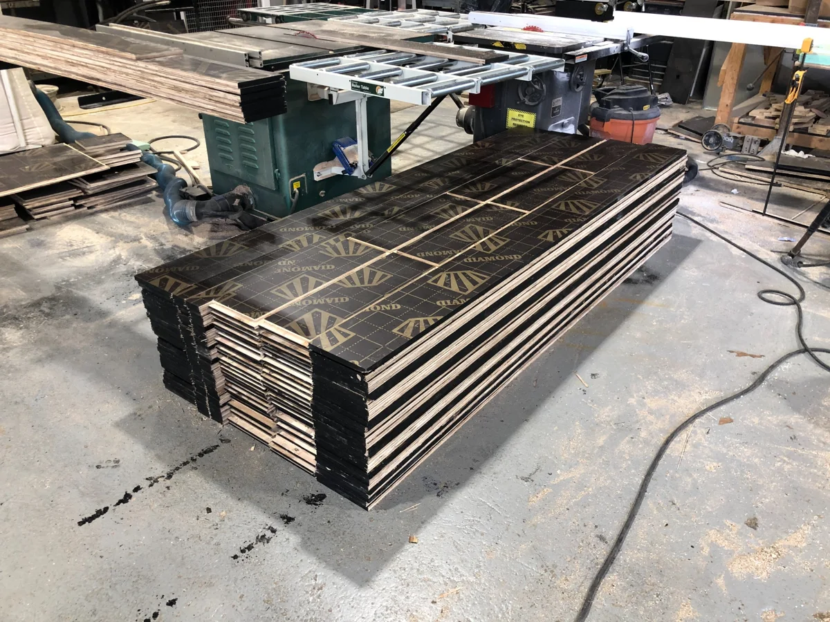
From routed components to site-ready formwork. · Starting at 1 of 5
Tekla Structures
I built 3D models of foundations and other concrete work from the architectural and structural drawing sets.
These models supported material takeoffs and layout drawings for crews using Trimble robotic layout equipment to locate column lines and concrete geometry. The model also became a reference when dimensions in the field did not appear to agree.
If someone on site called with a confusing dimension, I could check the modeled geometry and compare it with the drawings to help resolve the question. This made the model useful throughout construction, rather than only during initial planning.
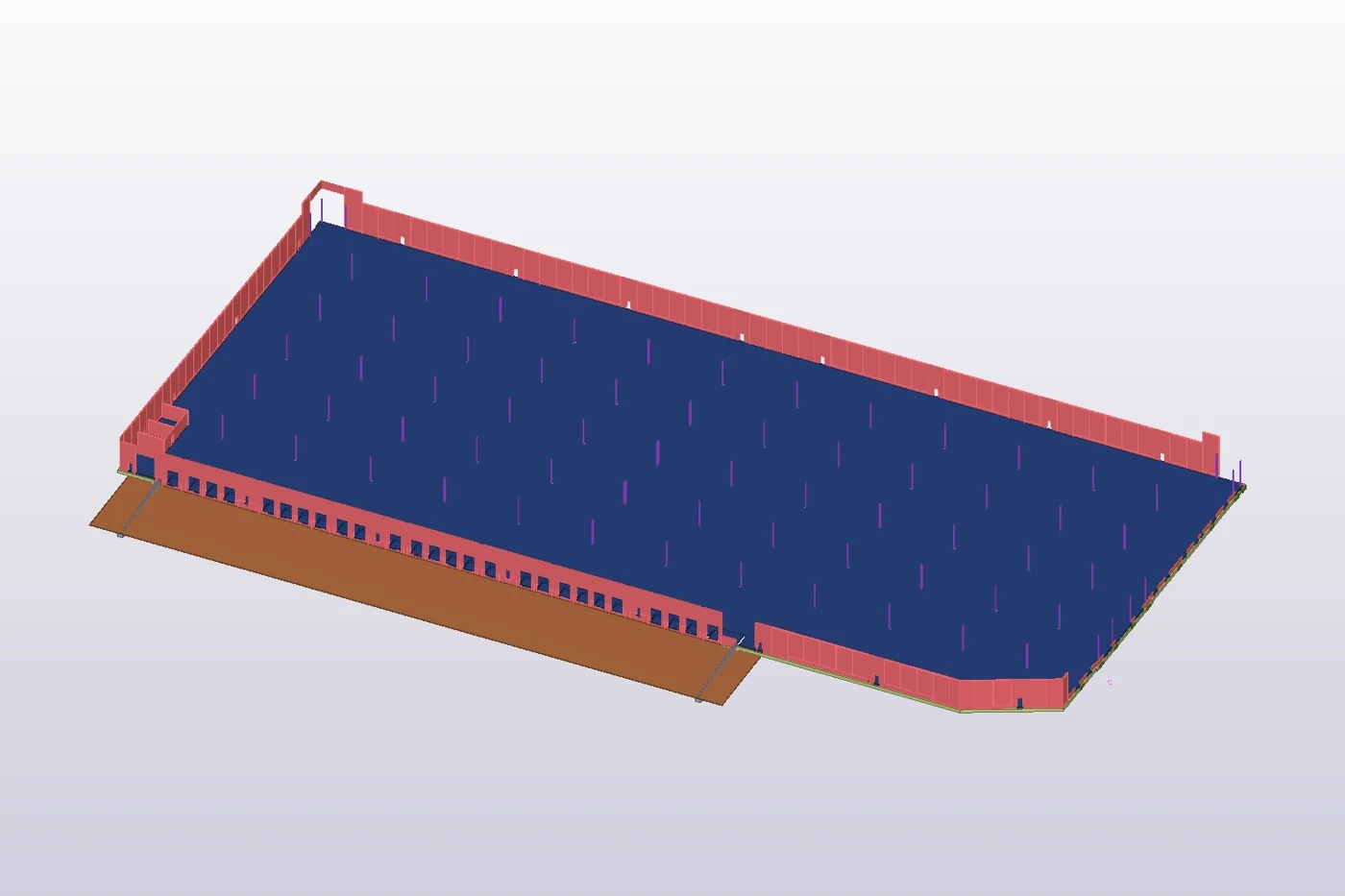
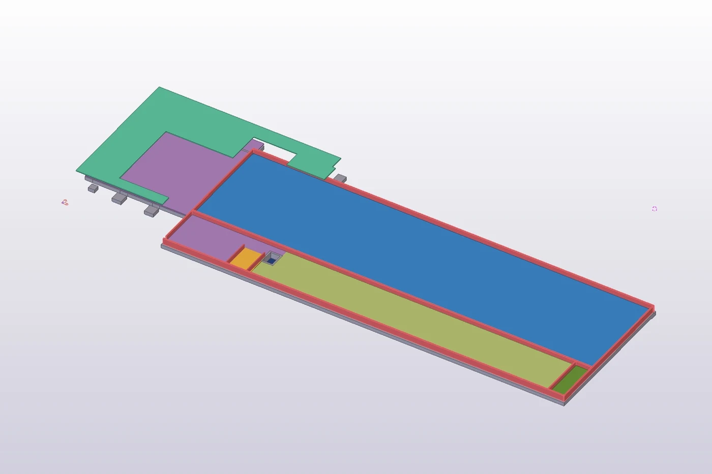
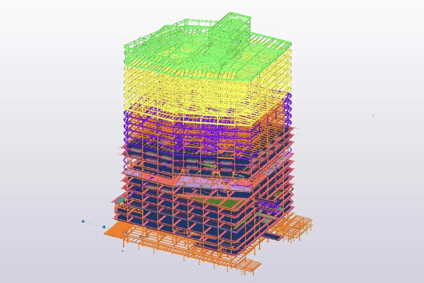
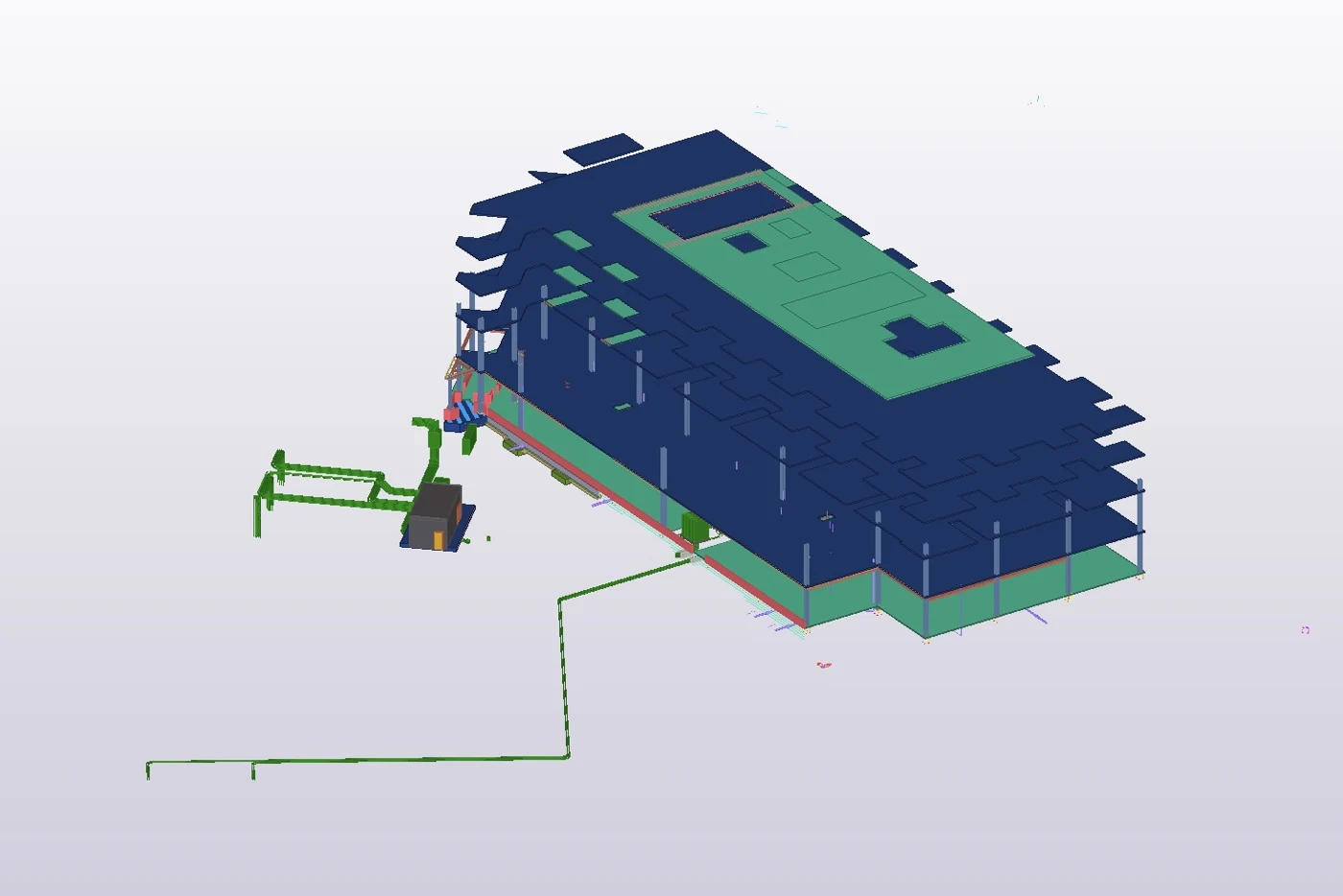
Selected digital models from my Tri-State work. · Starting at 1 of 4
Material quantities, field layout, dimensional checks, and communication between the office and the crews placing concrete.
In-house rebar process
Toward the end of my time at Tri-State, I became the company’s first person to produce rebar shop drawings in-house.
I took the structural engineer’s reinforcement details and sections and applied them across the concrete members in the model. My task was to turn those requirements into comprehensive placement drawings that showed the crews which bars belonged where before a pour.
The drawings included bar marks and schedules identifying the required pieces, quantities, sizes, lengths, and bend shapes. I also created identification tags so the fabricated material could stay connected to the drawing information.
Creating this workflow connected my Tekla work directly to the shop and the field. Seeing the reinforcement placed, the concrete poured around it, and the building grow above it made the impact of the work tangible.

Selected drawings
The formwork drawings show dimensions, bracing, assembly views, and piece schedules. The CHOP reinforcement sheets connect plan locations to structural sections, bar marks, and bend information.
Open any preview to inspect the drawing at a larger size.
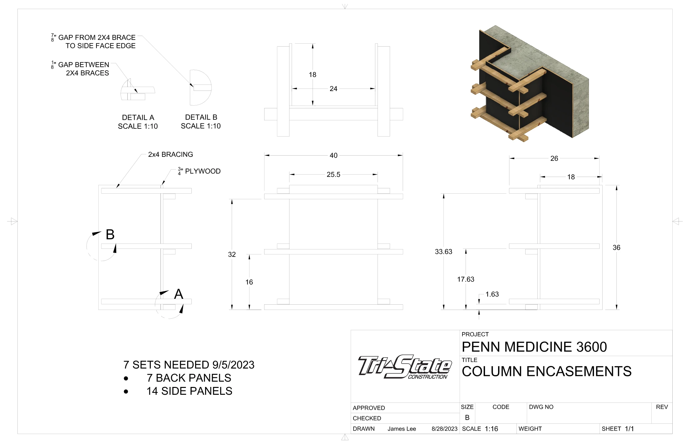
Penn Medicine 3600: assembly views, plywood and bracing details, dimensions, and required sets.
View drawing ↗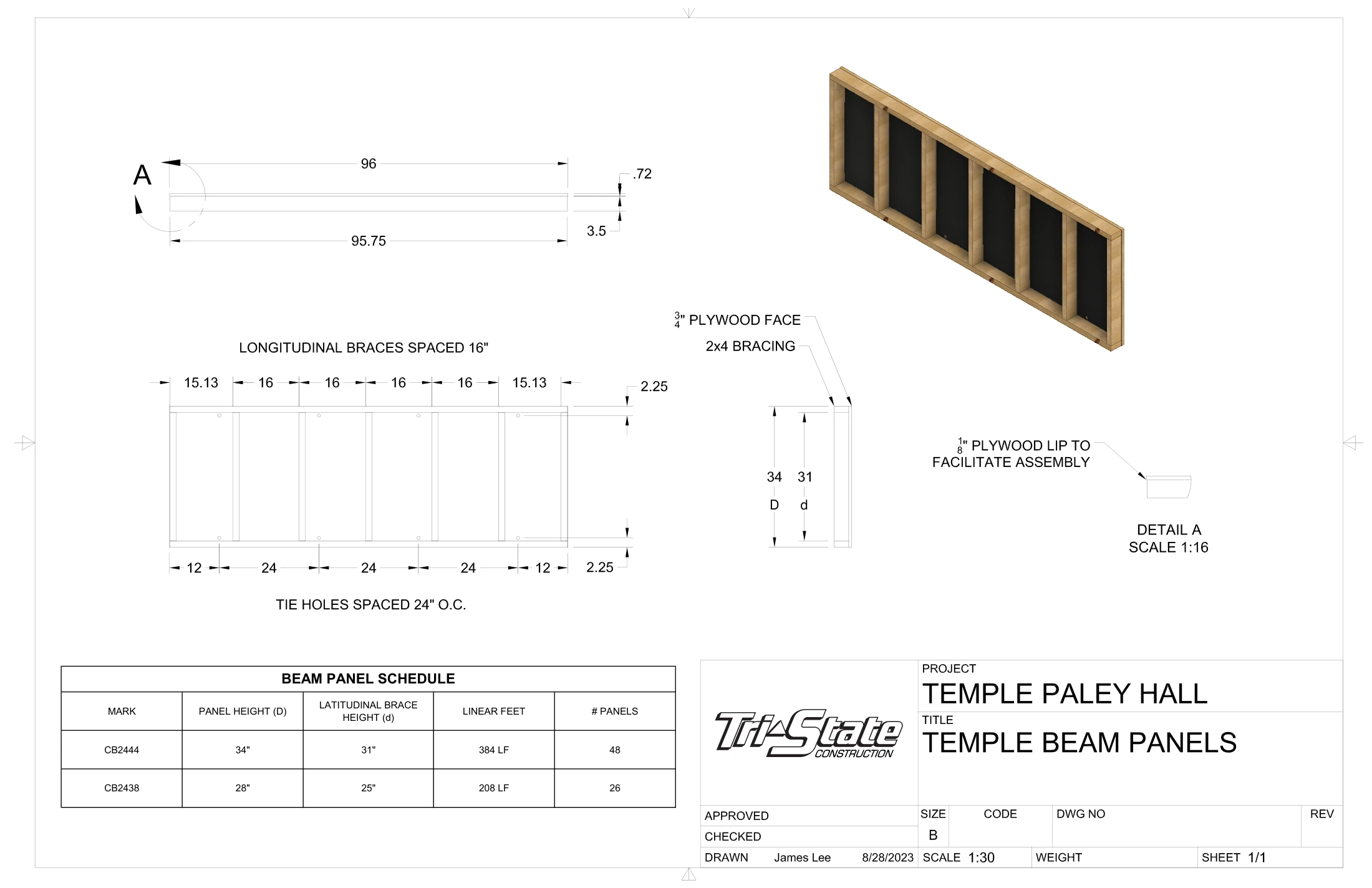
Temple Paley Hall: panel geometry, brace spacing, tie-hole locations, and a panel schedule.
View drawing ↗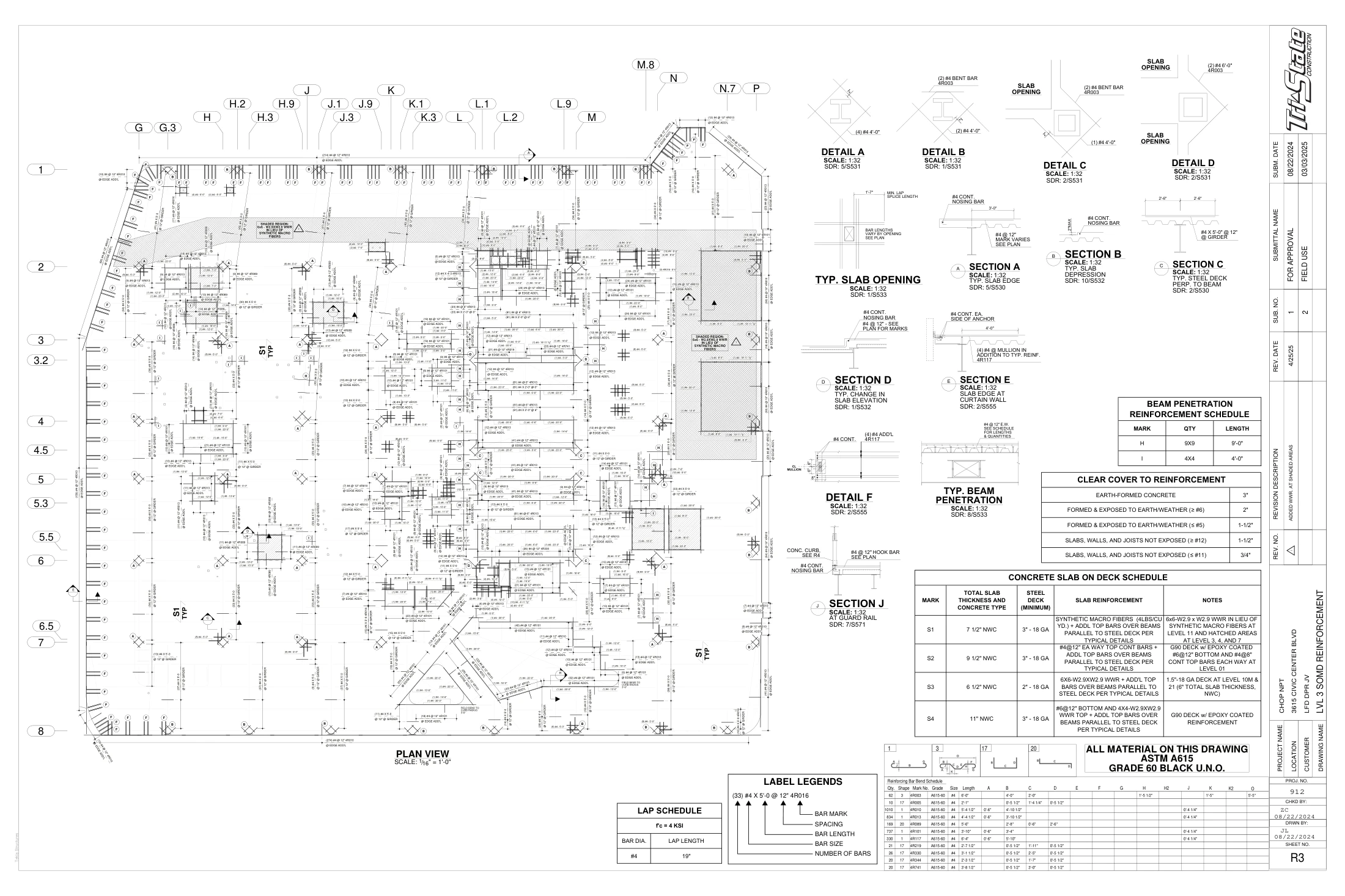
Level 3 slab-on-metal-deck reinforcement: plan, sections, placement callouts, and bend schedule.
View drawing ↗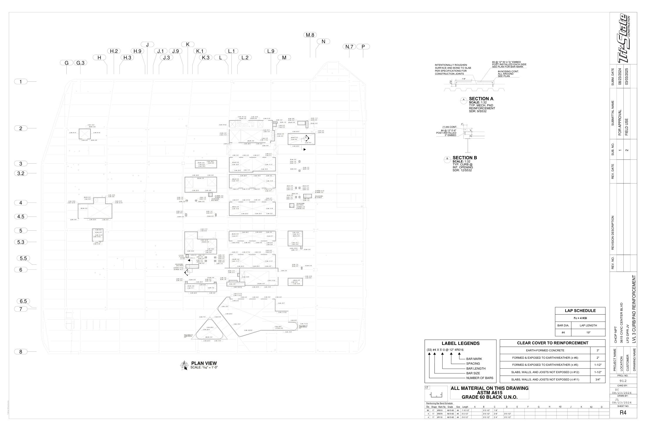
Additional reinforcement placement information from the three-sheet Level 3 shop drawing set.
View drawing ↗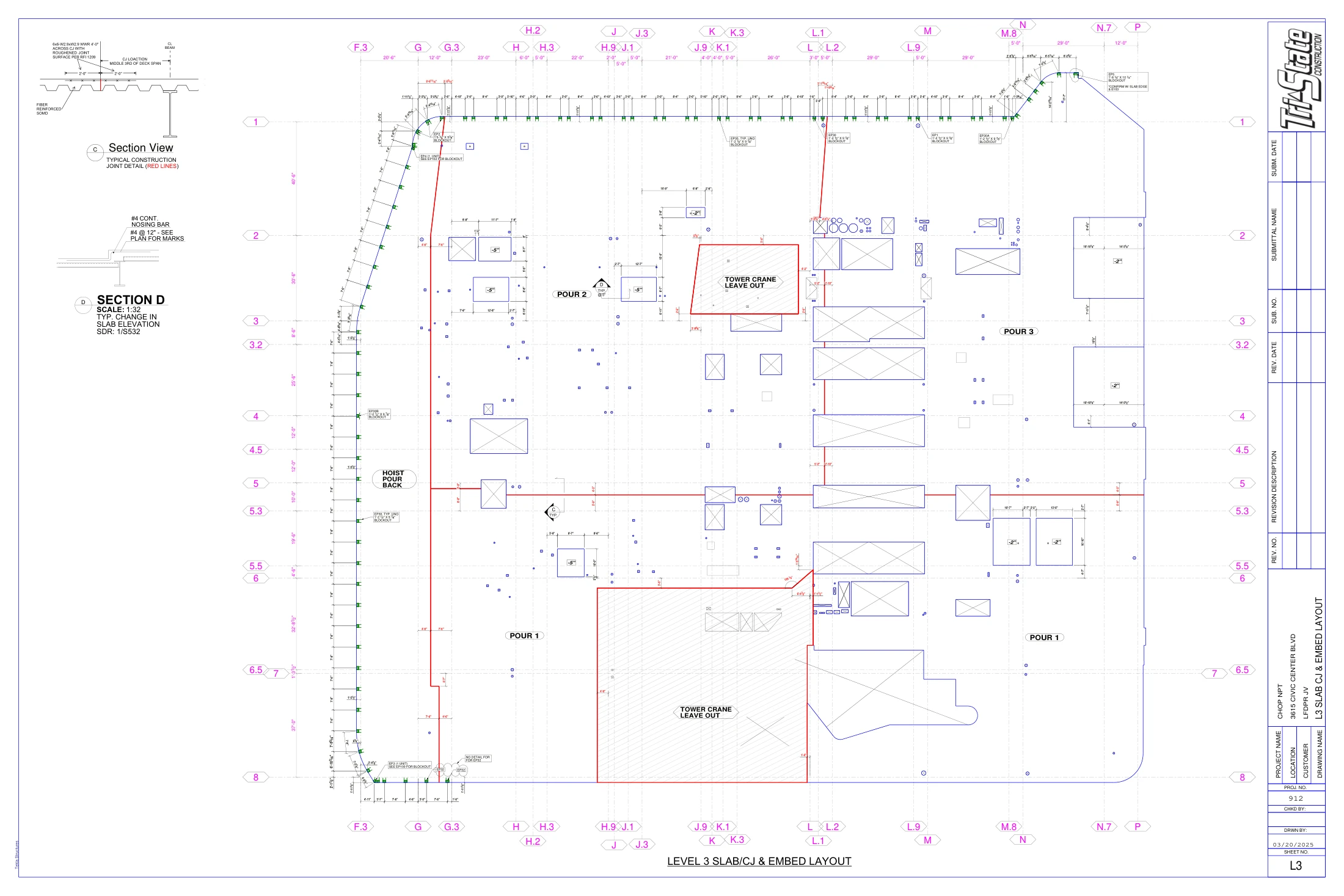
Further reinforcement details from the same shop drawing set.
View drawing ↗Project settings
My Tri-State work contributed to projects across healthcare, residential construction, education, and commercial development. My scope varied by project across formwork, concrete modeling, field coordination, and reinforcement detailing.
A drawing is only useful if someone can build from it. This work taught me to consider fabrication, identification, transport, installation, and field questions as part of the same engineering process.
Related experience
This construction and manufacturing experience shaped how I approach later aerospace projects and systems integration.
My professional background ↗← All projects